
Gas sensor chip

A gas sensor and chip technology, applied in instruments, scientific instruments, measuring devices, etc., can solve problems such as insufficient contact between chip electrodes and measuring gas, chip strength not meeting strength requirements, and affecting sensing effects, etc., to achieve compensation performance Can not take into account, simple structure, good selectivity effect

Inactive Publication Date: 2015-03-04
WUXI NUIST WEATHER SENSOR NETWORK TECH
View PDF7 Cites 0 Cited by
  • Summary
  • Abstract
  • Description
  • Claims
  • Application Information

AI Technical Summary

Problems solved by technology

[0014] The existing technology still has the following deficiencies: the strength of the chip cannot meet the required strength requirements, and the contact between the chip electrode and the measuring gas is not sufficient, which affects the sensing effect

Method used


Image

  • Gas sensor chip

Examples


Embodiment 1

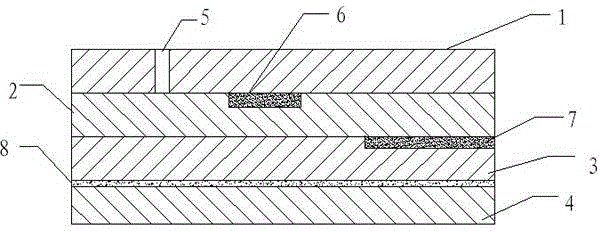
[0032] A gas sensor chip, which is formed by laminating four layers of piezoelectric substrates from the first layer to the fourth layer, wherein,

[0033] The first piezoelectric substrate 1 is provided with a reference gas channel 5;

[0034] A reference electrode 6 is arranged between the first piezoelectric substrate 1 and the second piezoelectric substrate 2, and the reference gas channel 5 communicates with the reference electrode 6;

[0035]A heating electrode 7 is arranged between the second layer of piezoelectric substrate 2 and the third layer of piezoelectric substrate 3, and the second layer of piezoelectric substrate 2 is coated with a gas sensitive film, and the sensitive film is Polymer membranes with adsorption and desorption properties for the corresponding gases;

[0036] A disordered metal film 8 is arranged on the fourth piezoelectric substrate 4 , and point electrodes are arranged on the disordered metal film 8 .

[0037] The manufacturing method of this...

Embodiment 2

[0044] A gas sensor chip, which is formed by laminating four layers of piezoelectric substrates from the first layer to the fourth layer, wherein,

[0045] The first piezoelectric substrate 1 is provided with a reference gas channel 5; the piezoelectric substrate is made of zirconia;

[0046] A reference electrode 6 is arranged between the first piezoelectric substrate 1 and the second piezoelectric substrate 2, the reference gas channel 5 communicates with the reference electrode 6, and the reference electrode 6 is covered with a porous alumina layer, and the reference gas channel 5 communicates with the porous alumina layer;

[0047] A heating electrode 7 is arranged between the second layer of piezoelectric substrate 2 and the third layer of piezoelectric substrate 3, and the second layer of piezoelectric substrate 2 is coated with a gas sensitive film, and the sensitive film is Polymer membranes with adsorption and desorption properties for the corresponding gases;

[00...


PUM


Abstract

The invention discloses a gas sensor chip. The gas sensor chip is formed by overlapping first, second, third and fourth layers of piezoelectric substrates, wherein a reference gas passage is arranged on the first layer of piezoelectric substrate; a reference electrode is arranged between the first layer of piezoelectric substrate and the second layer of piezoelectric substrate; the reference gas passage is communicated with the reference electrode; a heating electrode is arranged between the second layer of piezoelectric substrate and the third layer of piezoelectric substrate; the second layer of piezoelectric substrate is coated with a gas sensitive membrane; the gas sensitive membrane is a polymer membrane with adsorption and desorption properties towards the corresponding gas; a layer of disordered metal membrane is arranged on the fourth layer of piezoelectric substrate, and a point electrode is arranged on the disordered metal membrane. The gas sensor chip has the characteristics of high sensitivity, fast response, good selectivity, simple structure, long service life, and the like and can be designed aiming at any gas, thus overcoming the defect that traditional gas sensors can not have more properties at the same time.

Description

technical field [0001] The invention belongs to the technical field of sensor chips, and in particular relates to a gas sensor chip. Background technique [0002] With the improvement of automobile emission regulations, the requirements for exhaust emission control are also getting higher and higher. For this reason, automobile engines need a shorter cold start time to meet the requirements. At the same time, considering the needs of energy saving, a chip oxygen sensor with high integration, small size, low power consumption and fast start-up speed has become a trend to meet the requirements of the engine EFI system to enter closed-loop control as quickly as possible after cold start , while reducing the power consumption of the oxygen sensor. [0003] The existing chip sensor structure is mainly composed of three layers of zirconia substrate and several functional thick film layers. The zirconia substrate is mainly formed by casting or film rolling, and the thick film func...

Claims


Application Information

Patent Timeline
IPC IPC(8): G01N27/00
Inventor 禹胜林
Owner WUXI NUIST WEATHER SENSOR NETWORK TECH
Learn More