Method and device for monitoring pressure of test probe

A technology for testing probes and pressure, applied in measuring devices, mechanical pressure/force control, components of electrical measuring instruments, etc., can solve problems such as test deviation, affecting test results, and probe misjudgment, so as to reduce test errors Judgment rate, improve test stability, reduce impact and noise effects

Inactive Publication Date: 2015-03-04
HANS LASER TECH IND GRP CO LTD +1
View PDF7 Cites 16 Cited by
  • Summary
  • Abstract
  • Description
  • Claims
  • Application Information

AI Technical Summary

Problems solved by technology

[0003] At present, the test probe pressure control method of the flying probe testing machine in the prior art is: by controlling the test probe to lower the needle until the probe detection sensor triggers, and it is also necessary to manually adjust the pressure of the probe when the sensor triggers, manually Adjustment needs to be felt by experience, and it is very inconvenient to use; in the test, it cannot automatically detect and respond to the pressure change of the probe due to test fatigue and damage, which brings inconvenience to test operation and maintenance
In addition, if the pressure of the test probe changes during the test, the probe may be misjudged due to poor contact, which will affect the test result and efficiency. More importantly, during the entire test probe lowering and lifting process Among them, the motion control system cannot realize the process control of the test probe, which makes it impossible to combine the resources of the motion control system to optimize the test needle-down and needle-lift actions, which affects the effect of test probe pressure optimization to a certain extent.
[0004] It can be seen that the monitoring method in the prior art cannot monitor automatically, and it is easy to generate test deviation during the monitoring process, which affects the test effect, and also cannot combine system resources to achieve efficient testing.

Method used


Image

  • Method and device for monitoring pressure of test probe
  • Method and device for monitoring pressure of test probe

Examples


Embodiment Construction

[0030] In order to make the object, technical solution and advantages of the present invention clearer, the present invention will be further described in detail below in conjunction with the accompanying drawings and embodiments. It should be understood that the specific embodiments described here are only used to explain the present invention, not to limit the present invention.

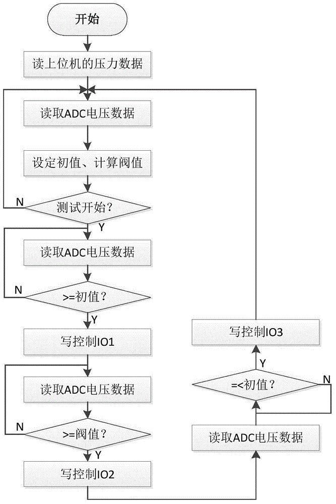
[0031] In the embodiment of the present invention, the pressure of the test probe is monitored by detecting the displacement of the test probe, and then the pressure of the test probe can be detected in real time from the displacement. When the initial value of the detection signal is detected, an indication signal is issued to indicate that the test probe has just come into contact with the workpiece, and the speed of the test probe lowering the needle is controlled to be reduced. When the displacement reaches the displacement of the preset pressure, the dynamic value of the detection signal is equ...


PUM


Abstract

The invention belongs to the technical field of machining of a PCB (Printed Circuit Board), and relates to a method for monitoring pressure of a test probe. The method comprises the following steps: detecting an initial position of the test probe and acquiring a detection signal initial value corresponding to the initial position; feeding the test probe; detecting current displacement of the test probe, acquiring a detection signal dynamic value of the pressure corresponding to the current displacement, and controlling the test probe to stop feeding when the detection signal dynamic value is equal to a detection signal threshold value corresponding to preset pressure. The invention also relates to a device for monitoring the pressure of the test probe. The device comprises a probe sensor, a sensor work and analog voltage output circuit, an analog-digital conversion module, a data processing module and a control module. According to the method and the device, the pressure of the test probe is automatically monitored and accurately adjusted, the impact and the noise during feeding of the test probe are reduced, an obvious pricking trace at the PCB testing point is avoided, the recognition of a probe lifting position is realized, the waiting time of positioning movement is reduced, the testing efficiency is improved, and the testing misjudgment rate is reduced.

Description

technical field [0001] The invention belongs to the technical field of PCB board processing, and in particular relates to a method and a device for monitoring the pressure of test probes of PCB test equipment. Background technique [0002] Flying probe testing machine is an automatic test equipment for PCB light board, which uses a high-speed moving test probe mechanism to realize the electrical characteristic test of PCB network. In order to avoid the hard landing of the test probe on the PCB, the carrier of the test probe is designed as a plastic spring. In order to make the probe contact with the PCB measuring point well and the PCB board under test will not be deformed, it is necessary to contact the PCB when the test probe After that, continue to load the appropriate pre-tightening pressure through the movement of the lower needle, which is the test probe pressure. The test probe pressure control is the key technology of the flying probe tester. The superior test probe...

Claims


Application Information

Patent Timeline
Patent Type & Authority Applications(China)
IPC IPC(8): G01R1/02G05D15/01
Inventor 黄俊华谭艳萍王星翟学涛高云峰
Owner HANS LASER TECH IND GRP CO LTD
Why Eureka
Try Eureka