Eureka AIR delivers breakthrough ideas for toughest innovation challenges, trusted by R&D personnel around the world.

Semi-automatic deburring machine

A deburring machine, semi-automatic technology, used in metal processing machinery parts, large fixed members, maintenance and safety accessories, etc., can solve the problems of unsuitable multi-variety and small batches, high skill requirements, high cost, and achieve high burr removal quality. , the overall structure is compact, the effect of occupying less space

Active Publication Date: 2015-03-11
六安永达机械股份有限公司
View PDF9 Cites 4 Cited by
  • Summary
  • Abstract
  • Description
  • Claims
  • Application Information

AI Technical Summary

Problems solved by technology

[0002] The removal of burrs on the gear end face is a difficult problem to solve. Although there are many methods available, there are some defects in different degrees.
For example, vibration deburring is easy to cause bumps and sand remains in the tooth groove; chemical deburring has a limit on the size of the burr, which affects the processing efficiency to a certain extent; special machine deburring has poor flexibility and high cost, so it is not suitable for small batches of many varieties; However, the traditional method of manual deburring on the drilling machine has low efficiency, low removal quality, easy damage to the tooth surface, and the splashed iron filings are more harmful to the operator's eyes. The working environment is very polluted, and after removing the burrs, iron filings must be specially thrown away, and the operator's skills are highly required

Method used


Image

  • Semi-automatic deburring machine
  • Semi-automatic deburring machine
  • Semi-automatic deburring machine

Examples


Embodiment

[0030] Embodiment: the semi-automatic deburring machine of the present embodiment comprises:

[0031] The gear lifting positioning device directly below the gear to be processed and the gear driving device directly above the gear;

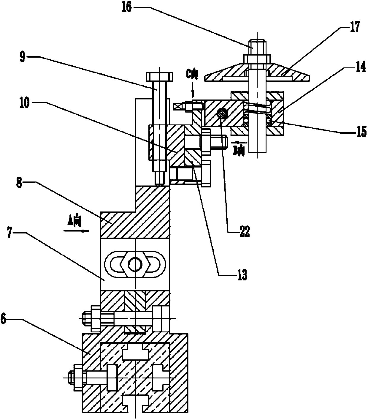
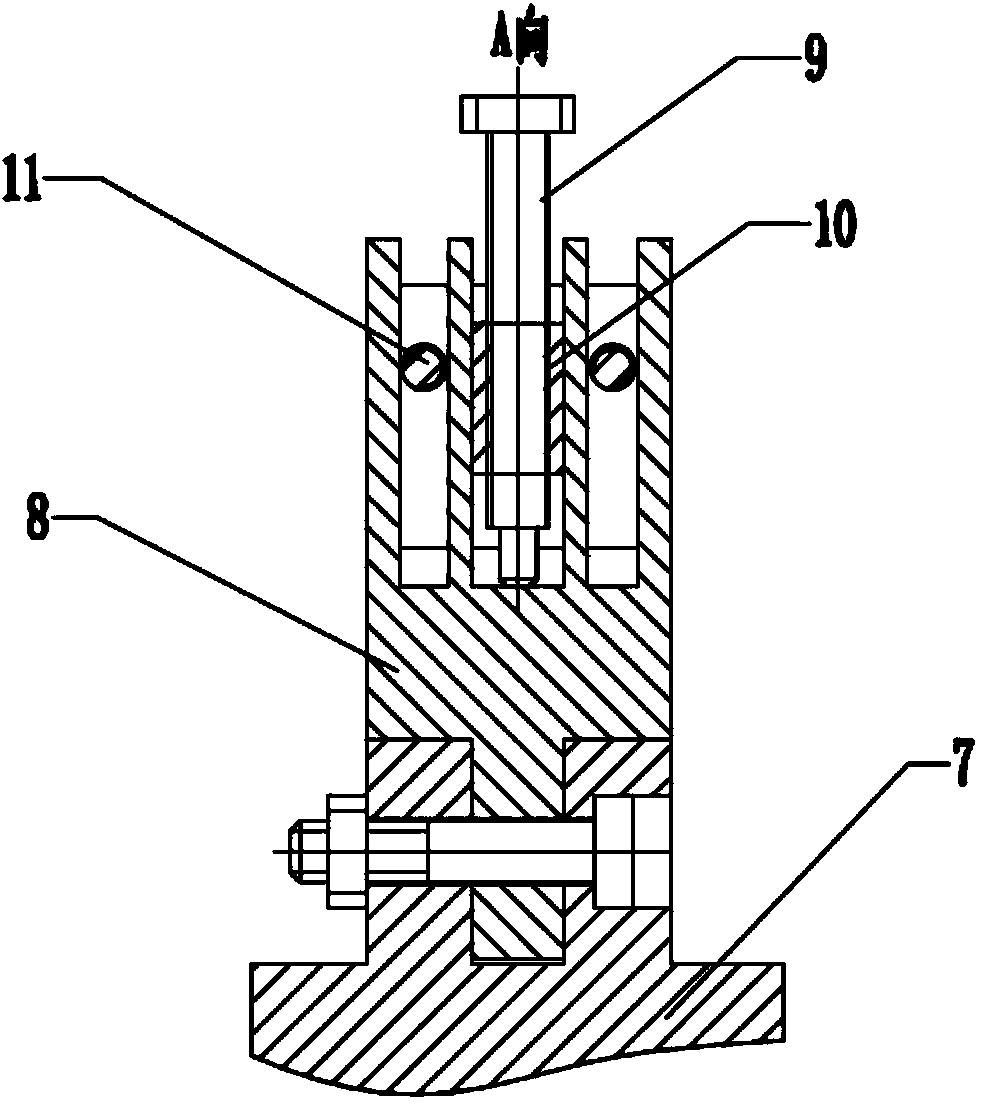
[0032] A deburring knife and a deburring knife support and adjustment device for deburring the gear end face;

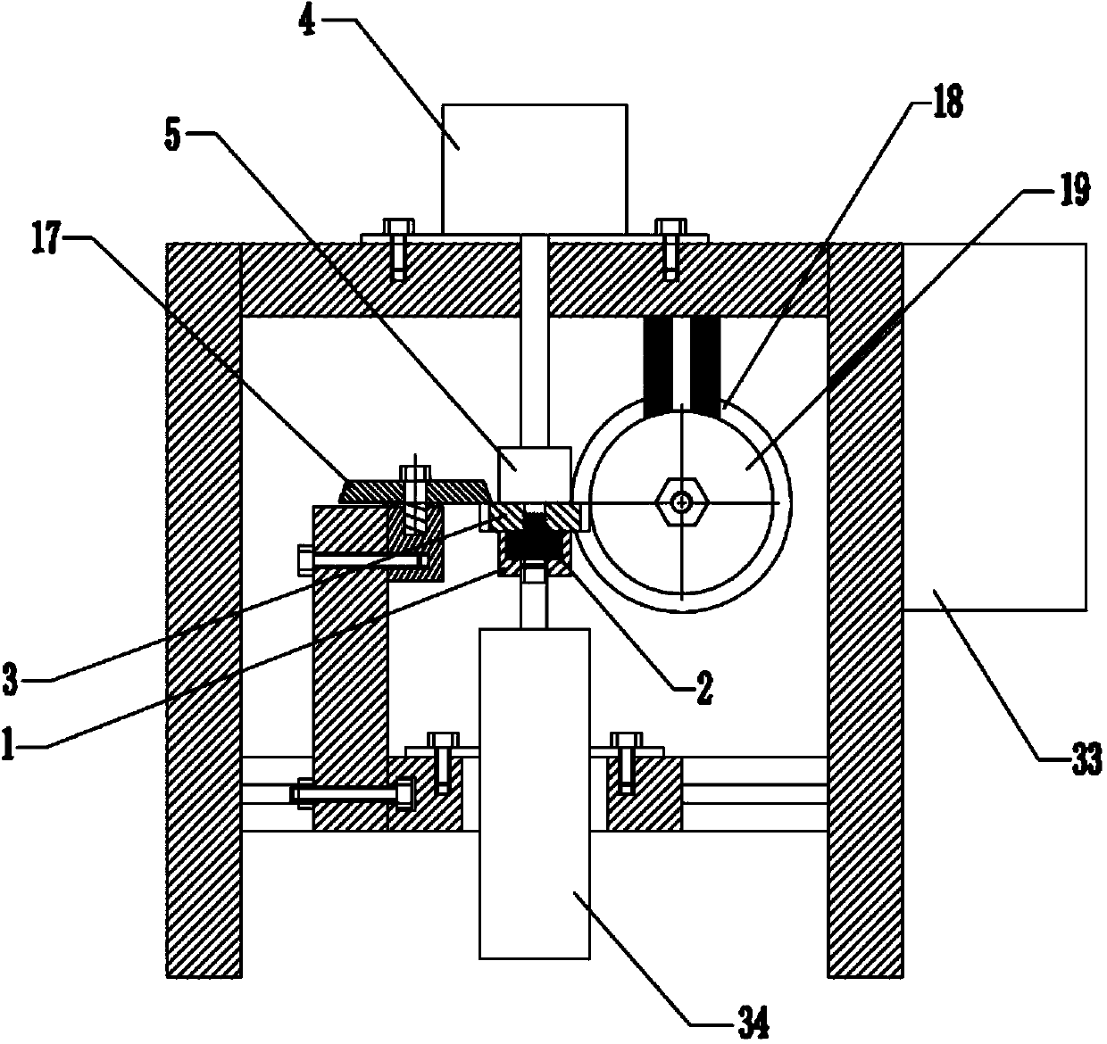
[0033] In specific settings, figure 1 As shown, the gear lifting positioning device includes: a connecting sleeve 1 that is threadedly connected with the cylinder piston rod, a gear mandrel 2 that is tightly matched with the step hole of the connecting sleeve, and the gear mandrel and the inner hole of the gear 3 are in clearance fit, and the gear can be in the Rotate horizontally on the gear mandrel.

[0034] The gear driving device includes a motor 4 arranged on the frame, and a friction wheel 5 arranged on the output shaft of the motor. The lower surface of the friction wheel contacts the upper surface of the gear to drive the gear t...


PUM


Abstract

The invention discloses a semi-automatic deburring machine. The machine comprises a gear propping, raising and positioning device arranged right below a gear to be processed, a gear driving device arranged right above the gear, a deburring cutter for deburring of a gear end face, and a supporting and adjusting device for the deburring cutter, wherein guide rails in X, Y and Z directions of the supporting and adjusting device for the deburring cutter can adjust the deburring cutter forward and rearward, right and left and up and down; a deburring cutter rotating shaft and a deburring cutter fixing seat which are arranged above the guide rail in the X direction can adjust the swing and the pitch of the deburring cutter, so that different gears can be processed, and helical gears at different spiral angles can be deburred. Similarly, support components of a polishing wheel can perform three-dimensional and pitch adjustment on the polishing wheel. The semi-automatic deburring machine disclosed by the invention has a simple, efficient, safe and stable gear deburring processing method.

Description

Technical field: [0001] The invention relates to a semi-automatic deburring machine. Background technique: [0002] The removal of burrs on the gear end face is a difficult problem to solve. Although there are many methods available, there are some defects in different degrees. For example, vibration deburring is easy to cause bumps and sand remains in the tooth groove; chemical deburring has a limit on the size of the burr, which affects the processing efficiency to a certain extent; special machine deburring has poor flexibility and high cost, which is not suitable for multiple varieties and small batches; However, the traditional method of manual deburring on the drilling machine has low efficiency, low removal quality, and easy damage to the tooth surface. The splashed iron filings are more harmful to the operator's eyes, and the cutting oil on the gear is splashed around due to centrifugal force. The working environment is very polluted, and after removing the burrs, i...

Claims


Application Information

Patent Timeline
Patent Type & Authority Applications(China)
IPC IPC(8): B23D79/04B23Q1/25B23Q11/00
Inventor 陶俊马全胜钱海生孙安全李杰陆舰
Owner 六安永达机械股份有限公司
Why Eureka
Eureka Blog
Learn More