Active suspension system for hydraulic type vehicle

An active suspension and suspension system technology, applied in suspension, elastic suspension, vehicle components, etc., can solve the problems of inaccurate control of compound valve flow, reduce the reliability of suspension system, and difficult to achieve active control, etc. The effect of improving ride comfort and operating stabilizers, improving fuel economy and low price

Inactive Publication Date: 2015-03-11
NORTHEAST AGRICULTURAL UNIVERSITY
View PDF8 Cites 22 Cited by
  • Summary
  • Abstract
  • Description
  • Claims
  • Application Information

AI Technical Summary

Problems solved by technology

Patent WO 2004 / 060702 A1 discloses a hydraulic active suspension system, which only solves the vibration of the vehicle when it encounters bumpy roads, but fails to solve the problem of body attitude changes caused by changes in the weight of the vehicle. And the use of hydraulic servo valve as the control valve of the hydraulic system leads to the disadvantages of high price of the entire hydraulic system and high requirements for the operating environment; however, the patent US6575484 B2 discloses a method that only solves the problem of changes in body posture due to changes in the weight of the body. In the patent US6394238 B1, although two systems are mentioned in the patent US6394238 B1, although the weight increment and the vibration of the road are considered, there are respective problems. The rodless chamber and the rod chamber of the cylinder are directly connected through the control valve, but a check valve and a throttle valve are installed at the piston of the damping hydraulic cylinder. This design can only allow the hydraulic oil from the system to enter the rodless chamber. However, the hydraulic oil in the rod chamber can only enter the rodless chamber and cannot be directly connected to the outside, which makes it difficult to realize real-time adjustable active control; the system mainly introduced in US6394238 B1 is improved on the basis of Figure 5, and the vibration The hydraulic cylinder directly connects the rodless cavity and the rod cavity through a compound valve composed of a one-way throttle valve and a relief valve connected in parallel, but the compound valve is not precise enough for flow control, and the circuits in these two patents also have structures Complexity and other problems greatly reduce the reliability of the suspension system; although the hydraulic suspension system mentioned in the paper "Vehicle Simulation for the Development of an Active Suspension System for an Agricultural Tractor" solves the above two vibration situations, the simultaneous selection The designed valves are relatively accurate, but there are problems in the design of the hydraulic system, which cannot form a complete oil return pipeline

Method used


Image

  • Active suspension system for hydraulic type vehicle

Examples


Embodiment Construction

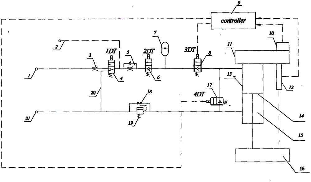
[0013] The present invention will be described in detail below in conjunction with the accompanying drawings.

[0014] A hydraulic vehicle active suspension system, the suspension system consists of a hydraulic pump 1, a throttle valve 3, a two-position three-way electromagnetic reversing valve 4, a one-way throttle valve 5, a two-position two-way electromagnetic ball valve 6, Two-position two-way proportional directional valve A8, damping hydraulic cylinder 14, overflow valve 19 and oil tank 21 are sequentially connected in series to form a closed-loop hydraulic system. The oil outlet of the hydraulic pump 1 is connected to the two-position three-way electromagnetic One end of the reversing valve 4 is connected, the other end of the two-position three-way electromagnetic reversing valve 4 is respectively connected with the oil inlet of the one-way throttle valve 5 and one end of the oil return pipeline 20, and the other end of the oil return pipeline 20 is connected with the o...


PUM


Abstract

The invention relates to an active suspension system for a hydraulic type vehicle and belongs to the technique of vehicle chassis. The suspension system is mainly composed of a closed loop hydraulic system which is formed by serially connecting a hydraulic pump, a throttle valve, a two-position tee solenoid directional valve, a one-way throttle valve, a two-position two-way electromagnetic ball valve, two-position two-way proportional direction valves, a vibration reducing hydraulic cylinder, an overflow valve and an oil tank in turn, wherein the connecting ends of the two-position tee solenoid directional valve and the one-way throttle valve are simultaneously connected with a system oil-supply pressure detecting line; a control unit is respectively connected with an acceleration sensor, a displacement sensor, the two-position tee solenoid directional valve, the two-position two-way electromagnetic ball valve, a two-position two-way proportional direction valve A and a two-position two-way proportional direction valve B through wires. A corresponding active force is generated by the system, so that the active control and the continuous control are realized; the vibration caused by an uneven pavement and increasing/reducing of vehicle weight is relieved; the structure is simple and reasonable; a control device is low in demand on an operation environment; the reliability is high; the manufacturing cost is low; the use cost is low; the hydraulic oil consumption is reduced; the fuel economy is increased.

Description

technical field [0001] The invention belongs to the technical field of vehicle chassis, and mainly relates to a hydraulic active suspension system which can obviously improve the ride comfort and operation stability of the vehicle. Background technique [0002] Suspension is one of the important assemblies on a modern car, elastically connecting the body with the axle (or wheel). Its main task is to transmit all the forces and moments acting between the wheels and the body, so as to ease the impact load transmitted from the road to the body and the driver, attenuate the vibration of the bearing system caused by it, and ensure the smoothness and handling of the car. stability. The performance of the suspension system has a great influence on the driving ability, handling performance, safety and other aspects of the car, so the suspension has always been one of the concerns of the car designers. At present, most of the traditional passive suspensions are used in the market. ...

Claims


Application Information

Patent Timeline
Patent Type & Authority Applications(China)
IPC IPC(8): B60G17/015B60G17/056
Inventor 迟媛李加奇纪翔宇任洁张荣蓉李寒寒
Owner NORTHEAST AGRICULTURAL UNIVERSITY
Why Eureka
Try Eureka