
A double-wall drill pipe reverse circulation drilling fixed guide impeller type swirl jet pump drill bit

A technology of guiding impeller and double-wall drill pipe, which is applied to drill bits, drilling equipment, earth-moving drilling, etc., can solve the problem that the bottom hole cuttings cannot be cleaned in time, the bottom hole cuttings return efficiency is reduced, and the rock breaking efficiency is affected. and other problems, to achieve the effect of improving the efficiency of rock cleaning, improving the efficiency of rock cleaning, and increasing the range of flushing.

Inactive Publication Date: 2017-02-01
CHINA UNIV OF PETROLEUM (BEIJING) +1
View PDF9 Cites 0 Cited by
  • Summary
  • Abstract
  • Description
  • Claims
  • Application Information

AI Technical Summary

Problems solved by technology

However, during the drilling process, the drilling fluid enters the inner pipe of the double-walled drill pipe from the flow conversion joint on the upper part of the bottom hole assembly, and the flow direction changes suddenly, which reduces the return efficiency of the bottom hole cuttings, and the bottom hole cuttings have to be Timely cleaning, resulting in repeated crushing of some rock debris, affecting rock breaking efficiency

Method used


Image

  • A double-wall drill pipe reverse circulation drilling fixed guide impeller type swirl jet pump drill bit
  • A double-wall drill pipe reverse circulation drilling fixed guide impeller type swirl jet pump drill bit
  • A double-wall drill pipe reverse circulation drilling fixed guide impeller type swirl jet pump drill bit

Examples


Embodiment Construction

[0022] Below in conjunction with accompanying drawing, illustrate the specific embodiment that the present invention proposes, structure, feature and effect thereof, detailed description is as follows:

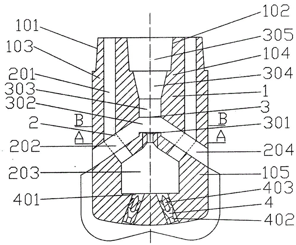
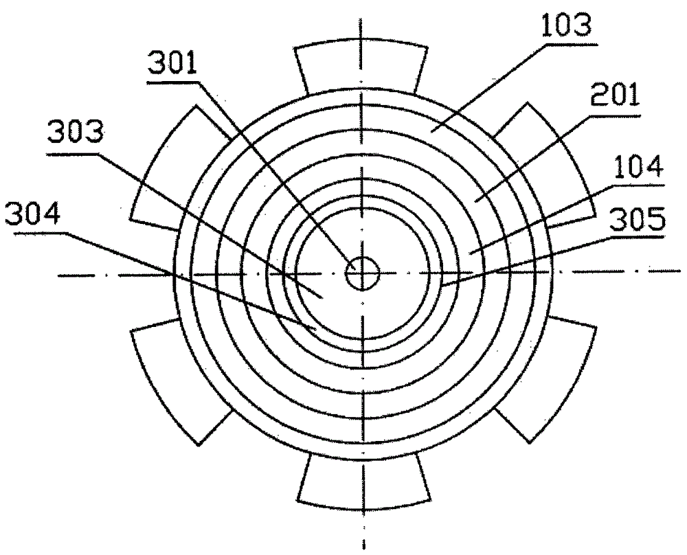
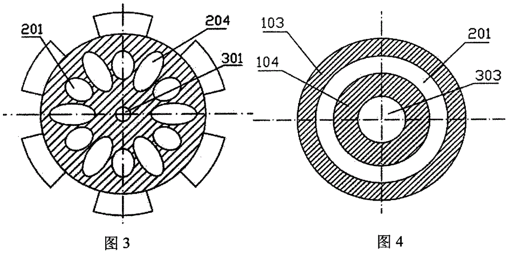
[0023] A double-wall drill pipe reverse circulation drilling fixed guide impeller type swirl jet pump drill bit, comprising a double-wall drill bit 1 and a bridge-type double-pipe flow channel 2 arranged inside the double-wall drill bit, a jet pump 3, and a fixed guide impeller type swirl jet pump Sand washing device 4.

[0024] The double-wall drill bit 1 comprises an outer pipe joint 101, an inner pipe joint 102, an outer pipe 103, an inner pipe 104, and a drill bit 105; the outer pipe joint 101 is connected with the outer pipe 103, and the outer pipe 103 is connected with the drill bit 105; The pipe 104 is connected, the inner pipe 104 is connected with the drill bit 105, the inner pipe joint 102 and the inner pipe 104 are located at the inside of the outer pipe joint 101 a...


PUM


Abstract

The invention discloses a double-wall drill pipe countercirculation well drilling fixed guide impeller type rotational flow and jet flow pump drill bit, which is characterized by comprising a double-wall drill bit, a bridge type double-pipe flow passage, a jet flow pump and a fixed guide impeller type rotational jet flow sand flushing device, wherein the bridge type double-pipe flow passage, the jet flow pump and the fixed guide impeller type rotational jet flow sand flushing device are arranged inside the double wall drill bit. The bridge type double-pipe flow passage replaces a flowing conversion joint arranged at the upper part of a bottom drill tool combination in a double-wall drill pipe countercirculation well drilling process, and the effect that well drilling fluid and rock chips directly enter the inner pipe of the double-wall drill pipe from a rock chip suction-in pipe of the double-wall drill pipe countercirculation well drilling fixed guide impeller type rotational flow and jet flow pump drill bit is achieved, so that the well bottom rock cleaning efficiency is improved, the jet flow pump sucks well bottom fluid, the well bottom pressure difference is reduced, the under balance is realized, and the mechanical drilling speed is accelerated. The fixed guide impeller type rotating jet flow sand flushing device generates high-speed rotating jet flow through a fixed guide impeller rotating jet flow spray nozzle, a well bottom rotational flow field favorable for rock cleaning is formed, the well bottom rock chip stress condition is improved, and the well bottom rock cleaning efficiency is improved.

Description

technical field [0001] The invention belongs to the field of drilling and oil and gas engineering, in particular to a double-wall drill pipe reverse circulation drilling fixed guide impeller type swirl jet pump drill bit. Background technique [0002] Double-wall drill pipe reverse circulation drilling (Reel Well drilling) is a new drilling technology, it is based on double-wall drill pipe, drilling fluid is pumped into the well from the double-wall drill Carry cuttings back to the ground, so as to realize the closed-loop circulation of drilling fluid. The double-wall drill pipe reverse circulation drilling technology was originally proposed to solve the problem of borehole cleaning in coiled tubing drilling. Since the double-wall drill pipe reverse circulation drilling technology was established in 2004, it has been mainly carried out by Statoil and the Norwegian Scientific Research Council for theoretical research, R&D and testing of supporting equipment. In 2005, the fe...

Claims


Application Information

Patent Timeline
Patent Type & Authority Patents(China)
IPC IPC(8): E21B10/60E21B10/61
CPCE21B10/60E21B10/61
Inventor 高德利陈绪跃郭柏云蒋凯张鑫朱海峰
Owner CHINA UNIV OF PETROLEUM (BEIJING)
Learn More