
Micro-electromechanical deformable structure and triaxial multi-degree of freedom micro-electromechanical gyroscope

A deformation structure, microcomputer technology, applied in gyroscope/steering sensing equipment, gyro effect for speed measurement, instruments, etc., can solve the driving and detection modal natural frequency offset, change the driving and detection modal matching, influence Gyroscope design performance and other issues, to achieve good measurement accuracy and sensitivity, compact structure, and little effect of temperature and processing errors

Active Publication Date: 2015-03-11
WEIFANG GOERTEK MICROELECTRONICS CO LTD
View PDF8 Cites 12 Cited by
  • Summary
  • Abstract
  • Description
  • Claims
  • Application Information

AI Technical Summary

Problems solved by technology

[0006] In addition, the performance of MEMS gyroscopes is greatly affected by environmental and process factors: when the ambient temperature changes, the dynamic characteristics of the sensitive structure of the gyroscope will change, causing the natural frequencies of the driving and detection modes to shift, thus changing the driving and sensing modes. Detect mode matching, resulting in differences in gyroscope performance at different ambient temperatures
When there are errors in the processing technology, the actual dynamic characteristics of the gyroscope will also have a large deviation from the design parameters, which will affect the realization of the design performance of the gyroscope.

Method used


Image

  • Micro-electromechanical deformable structure and triaxial multi-degree of freedom micro-electromechanical gyroscope
  • Micro-electromechanical deformable structure and triaxial multi-degree of freedom micro-electromechanical gyroscope
  • Micro-electromechanical deformable structure and triaxial multi-degree of freedom micro-electromechanical gyroscope

Examples


no. 1 example

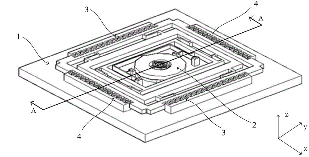
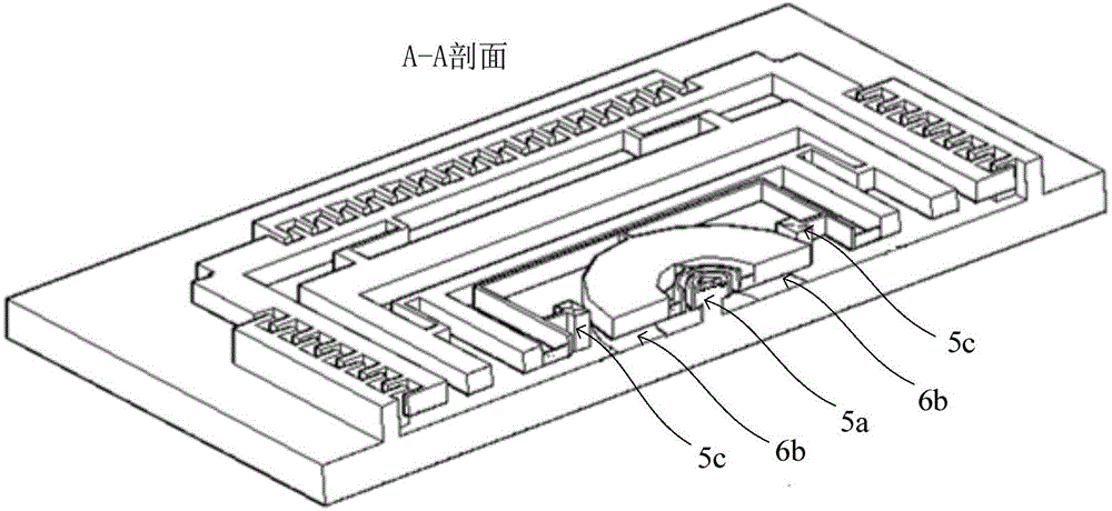
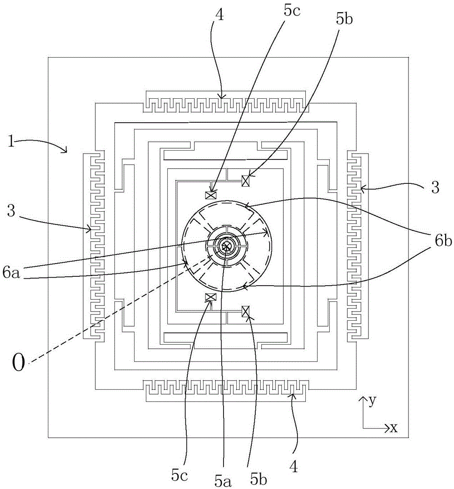
[0045] see Figure 1-Figure 4 It is the first embodiment of the three-axis multi-degree-of-freedom micro-electromechanical gyroscope of the present invention, including:

[0046] Substrate 1, there is a ring-shaped detection capacitor at the center of the substrate 1, defined with the center of the ring-shaped detection capacitor as the origin O, the plane where the substrate 1 is located is a spatial Cartesian coordinate system of the xy plane, and the z-axis of the spatial Cartesian coordinate system is perpendicular to the substrate 1.

[0047] The ring-shaped detection capacitor includes four lower plates fixed on the substrate 1 and a ring-shaped upper plate 2 facing the four lower plates and suspended above the lower plate. The shape of the upper pole plate 2 matches.

[0048] The four lower pole plates can be divided into two groups: the first group of lower pole plates 6a are symmetrically distributed on both sides of the origin along the x-axis and the two lower pole...


PUM


Abstract

The invention relates to a triaxial multi-degree of freedom micro-electromechanical gyroscope. The triaxial multi-degree of freedom micro-electromechanical gyroscope comprises an inner framework, a middle framework, an outer framework, a linkage part positioned in the inner framework, an annular detection capacitor positioned in the center, an annular polar plate of which outer edge of the annular polar plate is connected with the linkage part, two groups of driving capacitors and two groups of second detection capacitors, wherein the two groups of driving capacitors are symmetrically distributed on the two sides, parallel to an x axis, of the outer framework; the two groups of second detection capacitors are symmetrically distributed on the two sides, parallel to a y axis, of the outer framework. The triaxial multi-degree of freedom micro-electromechanical gyroscope adopts a single structure design, capacitance type electrostatic driving and differential capacitance detection; the driving mode is simple; as the structure is compact, the gyroscope size is reduced; the gyroscope is suitable for massive production, small errors are produced under the influence of temperatures and the processing technology, and great measurement precision and sensitivity can be realized.

Description

technical field [0001] The invention relates to microelectromechanical technology, in particular to a microelectromechanical deformable structure and a three-axis multi-degree-of-freedom microelectromechanical gyroscope. Background technique [0002] Micro Electro Mechanical System (MEMS), referred to as MEMS, is an emerging science and technology developed on the basis of microelectronics technology that integrates micro-machines, micro-sensors, micro-actuators, signal processing, and intelligent control. [0003] In MEMS measurement technology, deformable connection structures are often used, and its design is related to the feasibility of the measurement scheme, and its sensitivity is also related to the accuracy of the measurement. [0004] MEMS gyroscope is an inertial device based on MEMS technology, which is used to measure the angular velocity of object motion. It has the characteristics of small size, high reliability, low cost, and suitable for mass production, so...

Claims


Application Information

Patent Timeline
IPC IPC(8): G01C19/5684
CPCG01C19/5684
Inventor 张廷凯
Owner WEIFANG GOERTEK MICROELECTRONICS CO LTD
Learn More