Electromagnetic control device, in particular for adjusting camshafts of an internal combustion engine

A technology of adjusting device and camshaft, which is applied in the direction of electromagnet with armature, electromagnet, valve device, etc., can solve the problems of damage to the strength of the plunger, time-consuming, etc., and achieve the effects of simplified installation, cost-effectiveness, and simple manufacturing process.

Inactive Publication Date: 2019-11-19
KENDRION VILLINGEN GMBH
View PDF11 Cites 2 Cited by
  • Summary
  • Abstract
  • Description
  • Claims
  • Application Information

AI Technical Summary

Problems solved by technology

In addition to the time-consuming and additional cost of the additional heat treatment process, the strength of the plunger is generally compromised

Method used


Image

  • Electromagnetic control device, in particular for adjusting camshafts of an internal combustion engine
  • Electromagnetic control device, in particular for adjusting camshafts of an internal combustion engine
  • Electromagnetic control device, in particular for adjusting camshafts of an internal combustion engine

Examples


Embodiment Construction

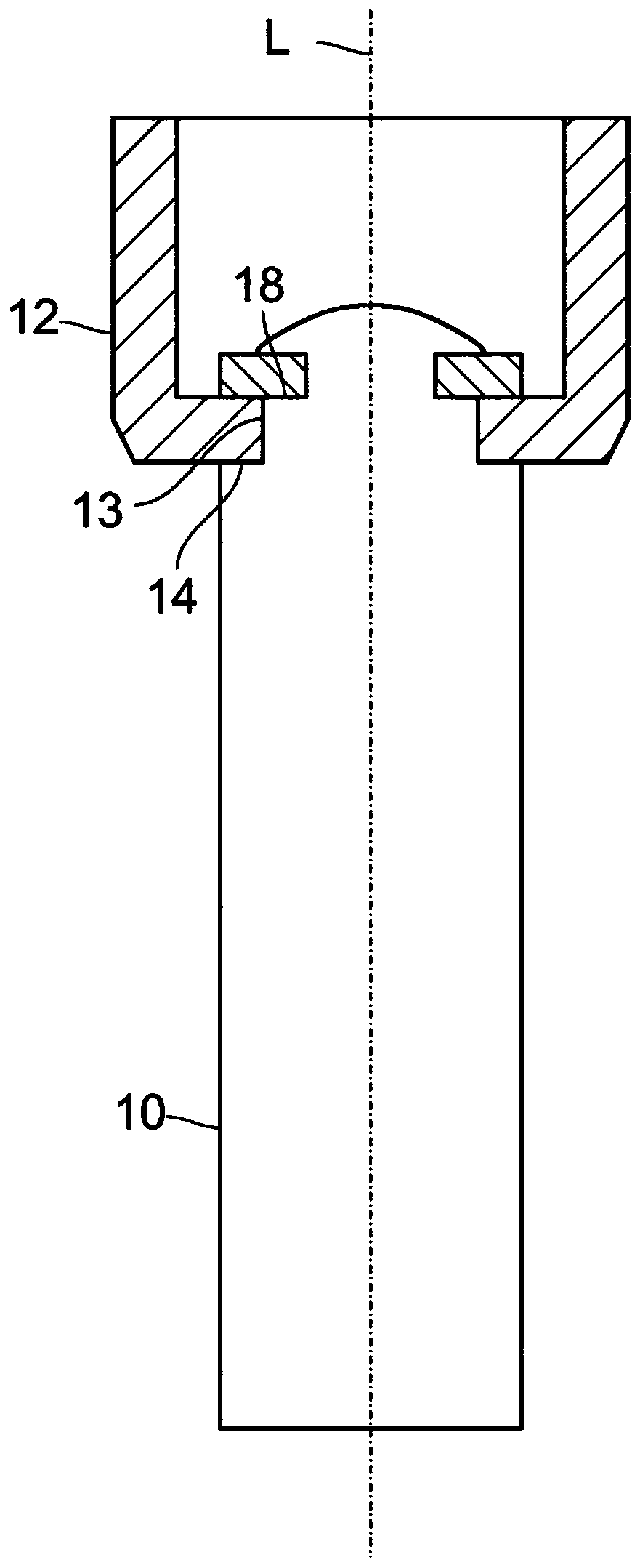
[0032] Figure 1a )with Figure 1b ) schematically shows the connection mode of the plunger 10 and the armature 12 in the prior art. refer to Figure 1a )with Figure 1b ), the plunger 10 is guided to move through the opening 13 of the armature 12 from below along the longitudinal axis L of the plunger 10 until the lower shoulder 14 of the plunger 10 fits on the armature 12 . Subsequently, the retaining washer 16 is introduced into the armature 12 from above and slid onto the plunger 10 until the retaining washer 16 rests on the upper shoulder 18 of the plunger 10 . The retaining washer 16 is dimensioned such that it protrudes radially beyond the opening 13 of the armature 12 . Subsequently, a punching tool (not shown) is introduced into the armature 12 from above, whereupon the plunger 10 is deformed so that the retaining washer 16 is fastened on the plunger 10 with a positive fit. The plunger 10 assumes a mushroom-like shape due to deformation. The position of the plunge...


PUM


Abstract

The present invention relates to an electromagnetic control device, in particular for adjusting camshafts or a camshaft section of an internal combustion engine, comprising an energisable coil unit (44), by means of which an armature (12) mounted for movement along a longitudinal axis (L) can be moved relative to a pole core between a retracted position and an extended position; a tappet (26), which is mounted for movement along the longitudinal axis (L) with a free end portion (28) with which, in the extended position, the tappet (26) interacts with a camshaft in order to adjust the camshaft,and with an inner end portion (30), with which the tappet (26) is attached to the armature (12), wherein the tappet (26) is attached in a form-fitting manner to the armature (12) by means of a deformable connection element. The invention also relates to a method for the form-fitting attachment of a tappet (26) to an armature (12) of an electromagnetic control device (42) of this kind.

Description

technical field [0001] The present application relates to an electromagnetic adjusting device, in particular for adjusting a camshaft of an internal combustion engine. Background technique [0002] The camshaft has many cams which represent eccentric sections on the camshaft. These cams can be arranged fixedly on the camshaft or on camshaft sections, which can be mounted in a rotationally fixed but axially displaceable manner on the cylindrical shaft. By rotating the camshaft, an assembly disposed adjacent to the cam and movable in the axial direction can move at regular intervals together with the cam. An application of the camshaft that deserves emphasis in this article is the opening and closing of valves in internal combustion engines. In modern internal combustion engines, the engine characteristics can be changed, for example, from an emphasis on comfort to sportiness, for example by changing the valve lift determined by the shape of the cam. Additionally, varying e...

Claims


Application Information

Patent Timeline
Patent Type & Authority Applications(China)
IPC IPC(8): F01L13/00H01F7/08
CPCF01L13/0036F01L2013/0052F01L2013/0078F01L2013/101F01L2810/04F01L2301/00F01L2303/00H01F7/127H01F7/1607H01F2007/086F01L1/047F01L2820/031
Inventor 比约恩·伯格菲尔德霍格尔·勃兰登堡
Owner KENDRION VILLINGEN GMBH
Why Eureka
Try Eureka