
Anti-falling convenient pin remover

A pin remover and anti-fall technology, which is applied to electrical components, overhead lines/cable equipment, insulators, etc., can solve the problems of low success rate of insulator pins, easy to fall from high altitude, and no anti-fall device for pin removers. , to achieve the effect of facilitating industrial production, reducing temperature and optimizing production process conditions

Inactive Publication Date: 2015-03-11
STATE GRID CORP OF CHINA +1
View PDF7 Cites 0 Cited by
  • Summary
  • Abstract
  • Description
  • Claims
  • Application Information

AI Technical Summary

Problems solved by technology

[0003] The purpose of the present invention is to provide a remote control gliding device for live work, which can solve the problems of low success rate when disassembling insulator pins, the traditional pin remover has no anti-falling device, and the pin remover is easy to drop from a high altitude.

Method used


Image

  • Anti-falling convenient pin remover
  • Anti-falling convenient pin remover
  • Anti-falling convenient pin remover

Examples


preparation example Construction

[0018] The present invention also includes a preparation method of an insulating sleeve, comprising the following steps:

[0019] (1) Mix 30-40 parts by weight of chlorosulfonated polyethylene rubber, 35-45 parts of polyurethane rubber and 20-30 parts of EPDM rubber into the internal mixer for 2-4 minutes , the banburying temperature is 90-100°C;

[0020] (2) Continue to add 2-4 parts by weight of antioxidant 4020, 2-10 parts of reinforcing agent, 5-8 parts of magnesium oxide, 10-15 parts zinc oxide, 3-7 parts of ethylene thiourea and 2-5 parts of calcium oxide, and continue banburying for 5-8 minutes; the reinforcing agent is white carbon black and aluminum hydroxide according to the weight of 2-4:1 ratio preparation;

[0021] (3) Adjust the temperature of the mill to 40-45°C, and mill the raw materials after step (2) for 4-8 minutes, then cool the material, and then put it into the mill, adding 10-15 parts by weight. Parts of tris (2-chloroethyl) phosphate, thin pass 2-4 ...

Embodiment 1

[0027]An insulating sleeve, in parts by weight, consists of the following components: 30 parts of chlorosulfonated polyethylene rubber, 35 parts of polyurethane rubber, 20 parts of EPDM rubber, 2 parts of anti-aging agent 4020, 2 parts of reinforcing agent, three 10 parts of (2-chloroethyl) phosphate, 5 parts of magnesium oxide, 10 parts of zinc oxide, 3 parts of ethylene thiourea and 2 parts of calcium oxide; the reinforcing agent is white carbon black and aluminum hydroxide at a ratio of 2:1 The weight ratio of the preparation.

Embodiment 2

[0029] An insulating sleeve, in parts by weight, consists of the following components: 40 parts of chlorosulfonated polyethylene rubber, 45 parts of polyurethane rubber, 30 parts of EPDM rubber, 4 parts of anti-aging agent 4020, 10 parts of reinforcing agent, three 15 parts of (2-chloroethyl) phosphate, 8 parts of magnesium oxide, 15 parts of zinc oxide, 7 parts of ethylene thiourea and 5 parts of calcium oxide; the reinforcing agent is white carbon black and aluminum hydroxide according to the ratio of 4:1 The weight ratio of the preparation.


PUM

PropertyMeasurementUnit
electrical resistivityaaaaaaaaaa

Abstract

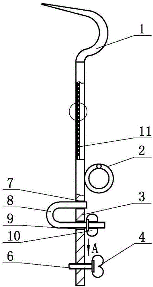
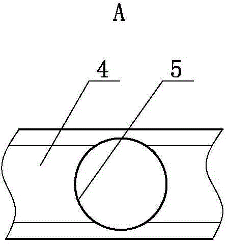
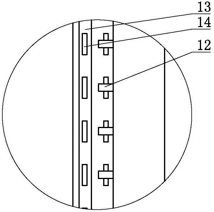
An anti-falling convenient pin remover comprises a connecting rod, the top of which is connected with one end of a U-shaped connecting rod; the other end of the U-shaped connecting rod is of a conical structure; an insulated bushing is sleeved at the middle part of the connecting rod and an anti-falling ring is fixed at one side of the connecting rod. The end of the pin recover is of a conical structure and can be easily inserted in a single insulator; when the single insulator is replaced and the pin is assembled / disassembled, the anti-falling convenient pin remover solves problems of increasing operator's working strength and working time, resulting from multiple repeated operations caused by operator's low success rate of assembling / disassembling the insulator pin at the first time. The anti-falling ring is arranged at one side of the anti-falling convenient pin remover, so that a rope can be conveniently twisted on the anti-falling ring and the falling of the anti-falling ring caused by the drop of the rope is avoided. The anti-falling convenient pin remover has the advantages of simple and compact structure, low manufacturing cost and convenience in use.

Description

technical field [0001] The invention relates to a pin remover, in particular to a drop-proof and convenient pin remover. Background technique [0002] In the process of replacing the single-piece insulator and installing the pin, the end of the pin remover is blunt and has a large end area, so it is not easy to insert the end of the pin remover into the single-piece insulator. Low cost, repeated operations are required, which increases the working intensity and working time of personnel; the traditional decanter has no anti-fall device, and the decanter is easy to drop from a high altitude, which poses a great hidden danger to the safety of operators. The anti-falling measure of the traditional depinner is just to tie the rope to the depinner, and the operation time is long, and the rope is easy to fall off. Contents of the invention [0003] The purpose of the present invention is to provide a remote control gliding device for live work, which can solve the problems of l...

Claims


Application Information

Patent Timeline
Patent Type & Authority Applications(China)
IPC IPC(8): H02G1/02H01B19/00
Inventor 杜远李鹏刘矞张健李增伟马玮杰王洪川袁孟男赵辛宋香涛吕修桐邹旭东马金龙张杨王龙逸逯遥
Owner STATE GRID CORP OF CHINA
Learn More