
Application device, removal device, application and removal system as well as application method, removal method, and application and removal method

A technology of a coating device and a coating method, which is applied in the direction of a device for coating liquid on a surface, a printing device, a spraying device, etc., and can solve the problems of increasing the cost and time of peeling off masking tape, waste of plating materials, and formation of difficult-to-dispose surfaces Masking and other issues

Inactive Publication Date: 2015-03-11
JE INT
View PDF8 Cites 4 Cited by
  • Summary
  • Abstract
  • Description
  • Claims
  • Application Information

AI Technical Summary

Problems solved by technology

However, in the technique described in Patent Document 1, since masking is performed with a masking tape, it is difficult to form a mask on a complex and small untreated surface.
In addition, when the masking tape is pasted only to the position that can be pasted, for example, when it is immersed in a plating solution, the plating solution is applied to unnecessary parts, thereby causing waste of plating materials.
[0005] In addition, since a peeling device for peeling off the masking tape must be provided, the cost and time required for peeling off the masking tape are increased.

Method used


Image

  • Application device, removal device, application and removal system as well as application method, removal method, and application and removal method
  • Application device, removal device, application and removal system as well as application method, removal method, and application and removal method
  • Application device, removal device, application and removal system as well as application method, removal method, and application and removal method

Examples


no. 1 Embodiment approach >

[0153] Next, a first embodiment of the present invention will be described with reference to the drawings. In addition, the dimensional ratios in the drawings may be different from actual ratios by exaggerating the ratios for the convenience of explanation.

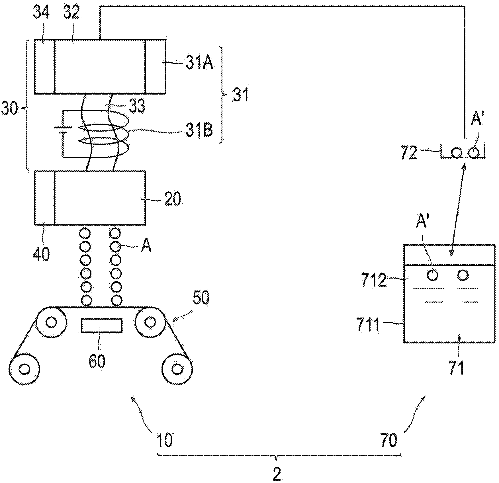
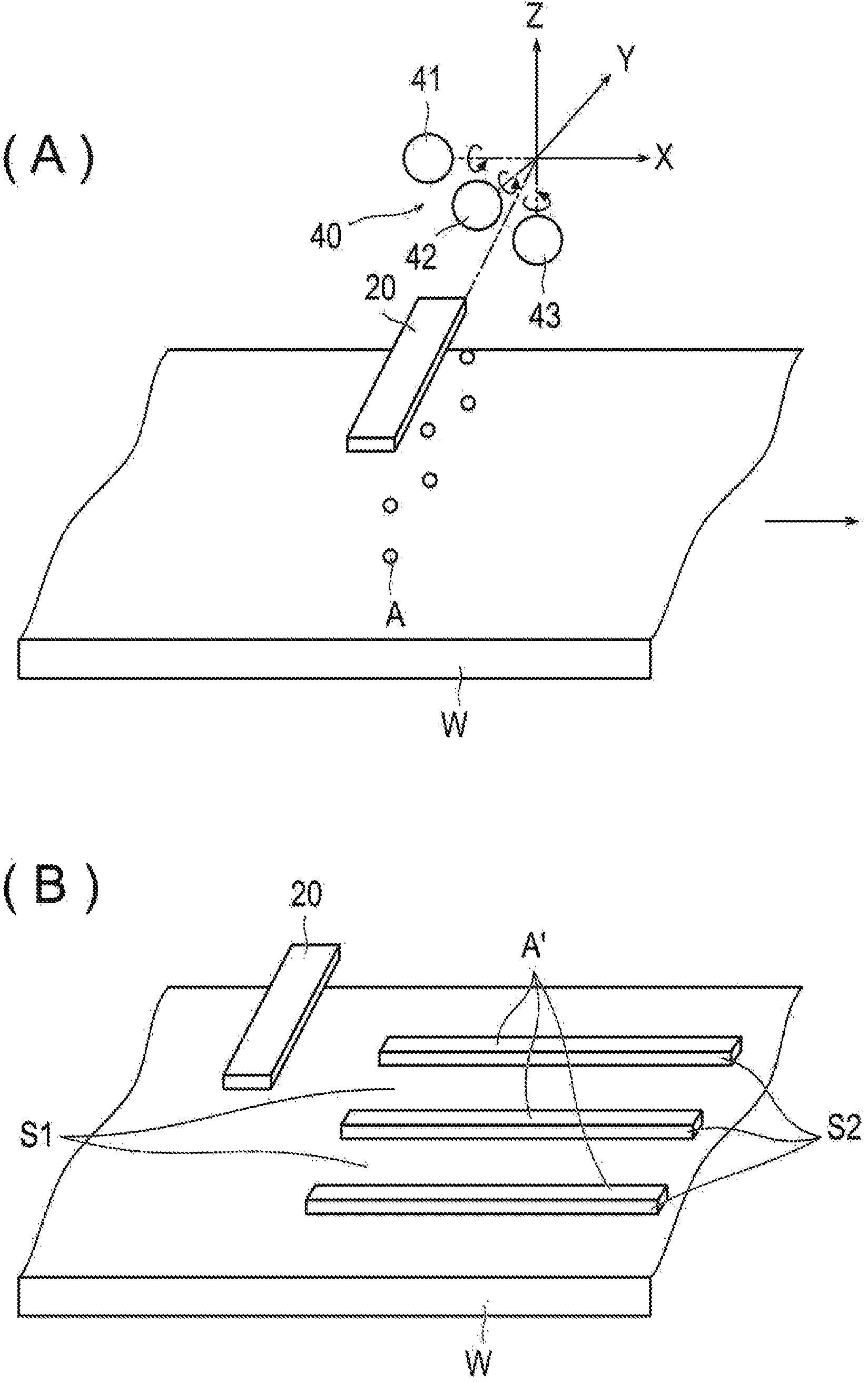
[0154] figure 1 It is a figure which shows the coating removal system 2 which concerns on 1st Embodiment of this invention. figure 2 (A) is a diagram showing a state in which the coating material A is applied to the non-treated surface S2 of the object W to be coated by the inkjet unit 20 of the coating device 10 according to the first embodiment, figure 2 (B) is a diagram showing the state of the object W after coating. in addition, figure 2 Among them, the direction in which the object to be coated W is conveyed is defined as the X direction (first direction), and the direction in which the rows of inkjet nozzles 24 of the inkjet unit 20 are arranged is defined as the Y direction (second direction), which is perpe...

no. 2 Embodiment approach >

[0233] Next, refer to Figure 10 , the coating removal system 5 according to the second embodiment of the present invention will be described. This embodiment differs from the first embodiment in that the removal device 170 further includes a melting removal unit 81 and a melting side recovery unit 82 . Hereinafter, the description of the parts common to the coating removal system 2 of the first embodiment will be omitted, and only the characteristic parts of the coating removal system 5 of the present embodiment will be described.

[0234] Coating removal system 5 of the present embodiment, such as Figure 10 As shown, there is a coating device 10 and a removal device 170 . The removal device 170 has a cooling removal unit 71 , a cooling side recovery unit 72 , a melting removal unit 81 , and a melting side recovery unit 82 . The configurations of the cooling removal unit 71 and the cooling side recovery unit 72 are the same as those of the first embodiment, and a detailed...

no. 3 Embodiment approach >

[0252] Next, refer to Figure 12 , the coating removal system 6 according to the third embodiment of the present invention will be described. This embodiment differs from the first and second embodiments in that the removal device 270 is composed of a melting removal unit 81 and a melting side recovery unit 82 .

[0253] Coating removal system 6 of the present embodiment, such as Figure 12 As shown, there is a melting and removing part 81, and the melting and removing part 81 is applied only to the non-treated surface S2 of the object to be coated W including the treated surface S1 subjected to surface treatment and the non-treated surface S2 not subjected to surface treatment. , the coating material A that is solid at room temperature and is liquefied by heating as a paraffin wax-containing masking agent A', the coating material A is melted into a liquid state by the liquid F1 having a temperature above the melting point of the paraffin wax and Remove from the object W to ...


PUM

PropertyMeasurementUnit
viscosityaaaaaaaaaa
melting pointaaaaaaaaaa

Abstract

The present invention is an application device (10) for applying a hot melt coating material (A) only on the non-treated surfaces (S2) of a coating object, which comprises treated surfaces (S1) where surface treatment is to be performed and non-treated surfaces (S2) where surface treatment is not to be performed, the device comprising: an inkjet unit (20) for discharging melted coating material (A) toward the coating object; a supply unit (30) for supplying the melted coating material (A) to the inkjet unit (20); and a heating means (31) for melting the coating material (A), the heating means being provided on the supply unit (30). Another invention removes coating material (A), which is a paraffin-containing masking agent and has been coated only on the non-treated surfaces (S2) of the coating object, still in solid form from the coating object using a refrigerant of a temperature less than the melting point of paraffin or in liquid form from the coating object using a fluid of a temperature at or above the melting point of paraffin. Said various configurations allow the formation of masking on small, complex non-treated surfaces as well as easy removal of the masking agent.

Description

technical field [0001] The invention relates to a coating device, a removal device, a coating removal system, a coating method, a removal method and a coating removal method. Background technique [0002] In surface treatment such as plating and etching, a masking agent is used to form a desired pattern. [0003] Conventionally, a non-treated surface of a substrate that is not subjected to surface treatment is covered with a masking tape, and then a predetermined surface treatment is performed, and the masking tape is peeled off by a predetermined peeling device (for example, refer to Patent Document 1). [0004] In recent years, along with the complexity of the shapes of electronic components and the like to be subjected to surface treatment, there has been an increasing demand for surface treatment on complex and small non-treated surfaces. However, in the technique described in Patent Document 1, since masking is performed with a masking tape, it is difficult to form a m...

Claims


Application Information

Patent Timeline
Patent Type & Authority Applications(China)
IPC IPC(8): B05C5/04B05D1/32
CPCH05K2203/013B41J2/17593B41J29/377H05K3/0091B41J2/01H01L21/56H05K3/288H05K3/28B05C5/001B05D1/32Y10T156/1911H05K3/125B05B3/021B05C11/1042B32B43/006
Inventor 金敏秀小西幸雄
Owner JE INT
Learn More