Cylinder assembly for a reciprocating piston combustion machine and cooling method

A technology of reciprocating pistons and internal combustion engines, which is applied to engine cooling, liquid cooling, cylinders, etc., and can solve problems such as increased fuel consumption, damage to parts, and heating

Inactive Publication Date: 2015-03-18
WAERTSILAE SCHWEIZ AG
View PDF1 Cites 1 Cited by
  • Summary
  • Abstract
  • Description
  • Claims
  • Application Information

AI Technical Summary

Problems solved by technology

This in turn can have the effect that the cooling water in the cylinder head is heated considerably, as a result of which, especially in the cylinder head, the formation of vapor bubbles in the coolant and / or vapor bubbles already formed in the cylinder liner can rise through the cooling system into the cooling cylinder head, as a result, the cooling in the cylinder head is impaired, which in the worst case leads to the cylinder head itself and / or components arranged at the cylinder head such as nozzles, outlet valves, hydraulic valves and Damage to devices, etc., as is well known to those of ordinary skill in the art, but either significantly shortens the service life of said components and / or adversely affects engine performance
[0008] Therefore, relevant parts such as the cylinder liner itself or at least the running surface of the cylinder liner, piston rings, pistons, cylinder head and components arranged therein (such as nozzles, outlet valves, significantly shortened service life of hydraulic valves and mountings, etc.) and has to account for power losses during engine operation which lead to increased fuel consumption and ultimately higher costs and reduced operating efficiency altogether

Method used


Image

  • Cylinder assembly for a reciprocating piston combustion machine and cooling method
  • Cylinder assembly for a reciprocating piston combustion machine and cooling method
  • Cylinder assembly for a reciprocating piston combustion machine and cooling method

Examples


Embodiment Construction

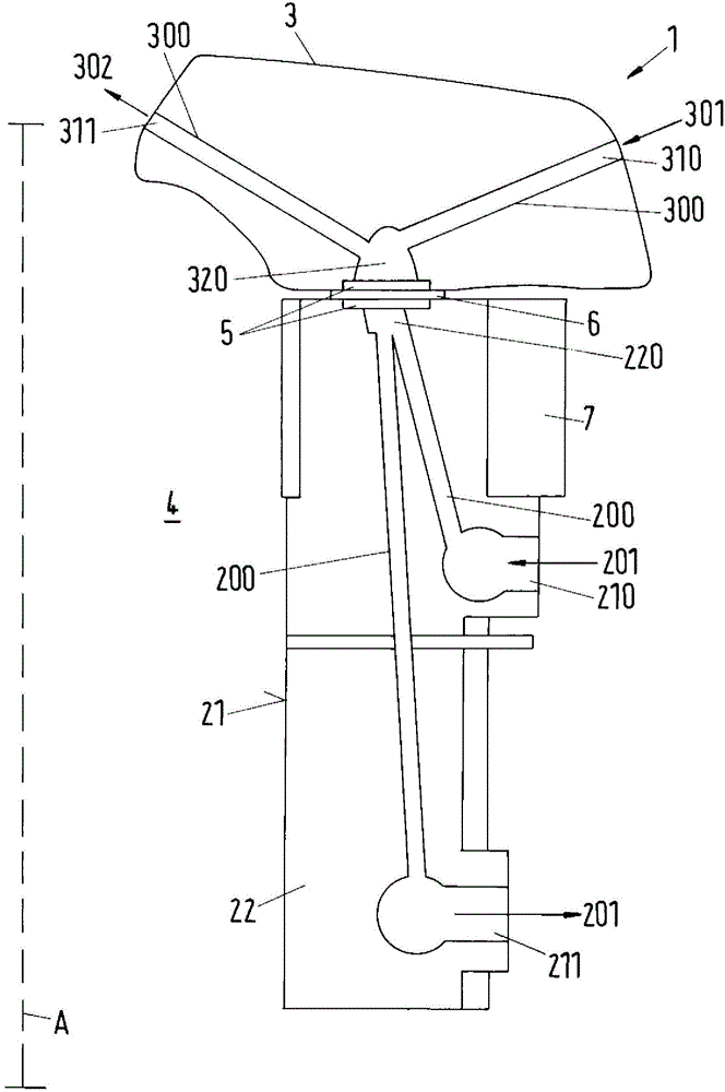
[0041] figure 1 A cylinder liner arrangement 1 according to the invention for a reciprocating piston internal combustion engine, in particular a longitudinally scavenged two-stroke large diesel engine, is shown schematically and only partially in section for the sake of clarity.

[0042] In this respect, the piston, shown not enlarged, is arranged in the cylinder liner 2 in a manner known per se, and in the operating and operating state the piston can thus be positioned in the upper center dead center position and the lower center position along the cylinder axis A of the cylinder liner 2 . Moving back and forth between the dead center positions, ie the upper side of the piston delimits the combustion space 4 together with the running surface 21 of the cylinder liner 2 and the cylinder head 3 arranged there.

[0043] The cylinder liner 2 comprises a liner cooling system 200 for cooling the cylinder liner 2 by means of a liner cooling fluid 201 , which in this example is coolin...


PUM


Abstract

The invention relates to a cylinder liner arrangement for a reciprocating internal combustion engine and a cooling method. The cylinder liner arrangement comprises a cylinder liner, in which a piston is installed, the factory and installed state between a top dead center and a bottom dead center so along a cylinder axis of the cylinder liner reciprocally disposed forth that a top of the piston delimits, together with a running surface of the cylinder liner and on the cylinder liner arranged in the cylinder cover a combustion chamber. The cylinder liner comprises a liner cooling system for cooling the cylinder liner by means of liner cooling fluid and the cylinder cover comprises a cover cooling system for cooling the cylinder cover by means of a cover cooling fluid, According to the invention, the liner cooling system in such a manner decoupled from the cover cooling system that a flow communication between the liner cooling fluid and the cover cooling fluid is controlled or regulated, or that the flow communication between the liner cooling fluid and the cover cooling fluid is prevented.

Description

technical field [0001] The invention relates to a cylinder liner arrangement for a reciprocating piston internal combustion engine, in particular a longitudinally scavenged two-stroke large diesel engine, and a cooling method for cooling the cylinder liner arrangement. Background technique [0002] Large diesel engines are often used as ship drive units or also during stationary operation, for example, to drive large generators to generate electricity. In connection with this, the engine is usually operated in continuous operation for a considerable period of time, which means stringent requirements with regard to effort and costs in terms of operational safety and availability. For this reason, in particular long maintenance intervals, low wear and economical maintenance of fuel and operating materials are the main criteria for the operator operating the machine. In particular, the piston movement behavior in the cylinder liners of such large-bore slow-running diesel engin...

Claims


Application Information

Patent Timeline
Patent Type & Authority Applications(China)
IPC IPC(8): F02F1/00
CPCF02F1/14F01P2003/027
Inventor G·布雷姆沙因
Owner WAERTSILAE SCHWEIZ AG
Why Eureka
Try Eureka