
Novel engine

An engine and steam technology, which is applied to engine components, combustion engines, machines/engines, etc., can solve problems such as high noise, flywheel operation, and increased engine damage, and achieve the effect of improving energy efficiency, low noise and reducing damage.

Inactive Publication Date: 2015-03-18
向前进
View PDF5 Cites 0 Cited by
  • Summary
  • Abstract
  • Description
  • Claims
  • Application Information

AI Technical Summary

Problems solved by technology

[0005] 2. The noise is high, and the energy of the source oil cannot fully make the flywheel run, which increases the damage of the engine

Method used


Image

  • Novel engine
  • Novel engine
  • Novel engine

Examples


Embodiment Construction

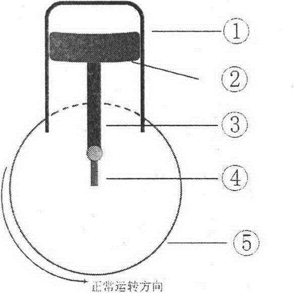
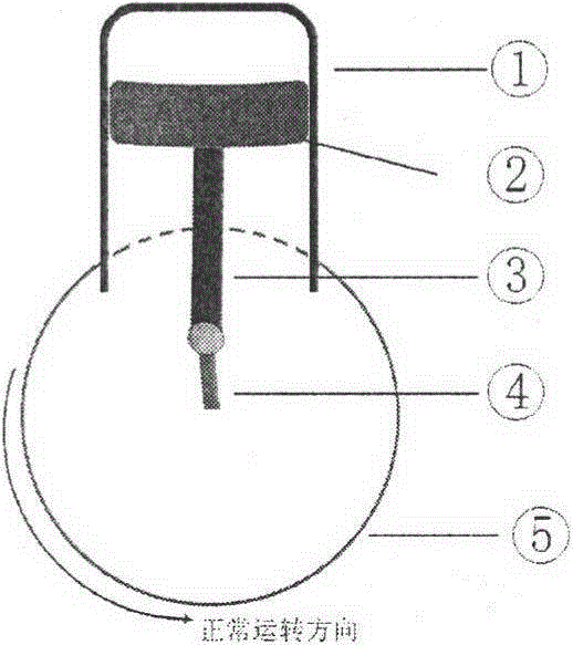
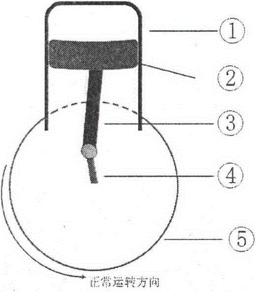
[0007] The original engine base will increase the connecting rod, and the compression cylinder will increase the steam nozzle. The connecting rod and the crank arm are in a straight line, and when the piston reaches the peak ( figure 1 ) does not spray source oil, when the crank arm rotates 2 degrees ( figure 2 ), when the piston drops a little, the temperature in the cylinder must be above the ignition point of the source oil to start injecting oil, and the crank arm turns another 2 degrees ( image 3 ), spray a small amount of boiling water vapor, the water absorbs the heat energy released by the source oil and decomposes into hydrogen and oxygen, because the expansion coefficient of water decomposed into hydrogen and oxygen is greater than the expansion coefficient of air, thus improving the efficiency of starting. At the same time, the oxygen content in the cylinder is increased, the combustion speed of the source oil is accelerated, the combustion is more complete, and ...


PUM


Abstract

The invention discloses a novel engine. The engine has the advantages that the energy of cooling water is recyclable and can be converted to kinetic energy, and the effective rate of energy is increased; noise is low, and the oil energy allows flywheels to run fully so as to decrease the damage to the engine; spark plug ignition is replaced with combustion by chemical combination after water decomposition in high temperature environment.

Description

1. Technical field: [0001] 1. The cooling water energy is reused and converted into kinetic energy to improve energy efficiency. [0002] 2. The noise is low, and the energy of the source oil is sufficient to make the flywheel run, thus reducing the damage of the engine. [0003] 3. Use water to decompose in high temperature environment and then combust instead of spark plug to ignite. 2. Background technology: [0004] 1. The efficiency of the current engine is low, and the heat energy in the cooling water is all wasted. [0005] 2. The noise is high, and the energy of the source oil cannot fully make the flywheel run, which increases the damage of the engine. 3. Contents of the invention: [0006] The present invention is a method that can reuse the cooling water energy and turn it into kinetic energy to improve the energy efficiency. The energy of the source oil can fully make the flywheel run, thus reducing the damage to the engine and reducing the noise at the same ...

Claims


Application Information

Patent Timeline
Patent Type & Authority Applications(China)
IPC IPC(8): F02M25/022F02M25/10
CPCY02T10/12
Inventor 向前进
Owner 向前进
Learn More