Two-stage screw compressor

A screw compressor and body technology, applied in mechanical equipment, machines/engines, liquid fuel engines, etc., can solve the problems of uneven mixing of oil and gas, increase the vibration and noise of screw compressors, poor cooling effect, etc., and achieve a wide range of gas volumes. Matching requirements, reducing vibration and noise, and ensuring stable operation

Pending Publication Date: 2022-05-13
SHANGHAI POWER TECH SCREW MACHINERY
View PDF0 Cites 0 Cited by
  • Summary
  • Abstract
  • Description
  • Claims
  • Application Information

AI Technical Summary

Problems solved by technology

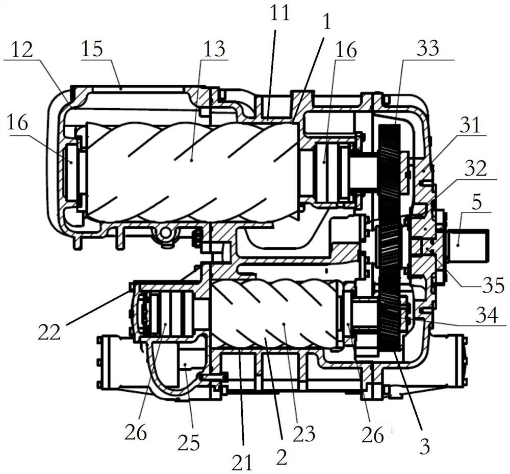
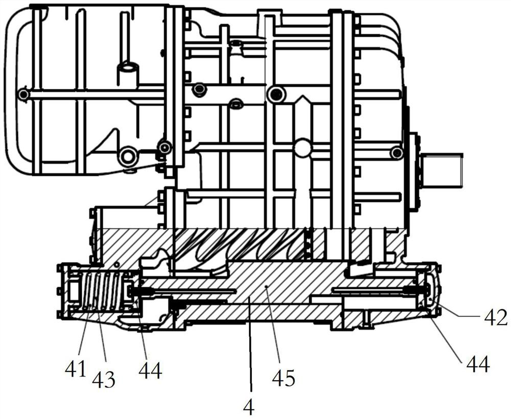
[0004] The traditional two-stage compression screw compressor adopts upper and lower arrangements. Usually, the first-stage body and the second-stage body are one casting, and a connecting channel is arranged inside. The channel is separated from the gearbox, and a driving gear is used to drive the two. Driven gear, the two driven gears are respectively connected with the male rotor of the low-pressure stage and the male rotor of the high-pressure stage, and the structure is complex
[0005] For this two-stage screw main engine, the integrated body is too large, heavy, and complex in structure; the gear pair includes a driving gear and two driven gears, and the gear consumes a lot of power, which requires oil injection to lubricate and cool the gear pair ; Interstage oil injection cooling is prone to uneven oil and gas mixing, and the cooling effect is poor, which affects the efficiency of the compressor
At the same time, when faced with different pressure demands from users, processing and shaping the exhaust port will cause the compression process of the compressor to be over-compressed or under-compressed. Over-compression or under-compression will not only cause additional power consumption, but also increase Vibration and Noise During Operation of Large Screw Compressor

Method used


Image

  • Two-stage screw compressor
  • Two-stage screw compressor
  • Two-stage screw compressor

Examples


Embodiment Construction

[0031] Preferred embodiments of the present invention will be described in detail below in conjunction with the accompanying drawings.

[0032] In order to further understand the present invention, the preferred embodiments of the present invention are described below in conjunction with examples, but it should be understood that these descriptions are only to further illustrate the features and advantages of the present invention, rather than limiting the claims of the present invention.

[0033] The description in this part is only for several typical embodiments, and the present invention is not limited to the scope of the description of the embodiments. The mutual replacement of the same or similar prior art means and some technical features in the embodiments is also within the scope of the description and protection of the present invention.

[0034] "Connection" in the specification includes both direct connection and indirect connection.

[0035] The invention disclos...


PUM


Abstract

The invention discloses a two-stage screw compressor which comprises a first-stage screw compressor, an interstage gearbox, a second-stage screw compressor and a flexible internal volume ratio slide valve, the first-stage screw compressor comprises a first machine body, a low-pressure-stage male rotor, a low-pressure-stage female rotor and a low-pressure-stage air suction end body; the second-stage screw compressor comprises a second machine body, a high-pressure-stage male rotor, a high-pressure-stage female rotor and a high-pressure-stage exhaust end body; a mechanical mixer is arranged in the interstage gearbox; the second-stage screw compressor is provided with the flexible internal volume ratio slide valve; according to the flexible internal volume ratio slide valve, the position of the slide valve can be automatically adjusted according to the pressure difference of the high-pressure cavity and the low-pressure cavity, so that the optimal internal volume ratio is obtained. According to the two-stage screw compressor, interstage cooling and the optimal internal compression process can be effectively achieved, then the efficiency of the compressor is improved, meanwhile, an oil-gas mixture flowing through the speed increasing gear lubricates and cools the gear, and stable operation of the gear is guaranteed.

Description

technical field [0001] The invention belongs to the technical field of screw compressors, and relates to a screw compressor, in particular to a two-stage screw compressor. Background technique [0002] The working process of the two-stage compression screw compressor is that the gas enters the first-stage working chamber, is compressed and pressurized after being mixed with lubricating oil in the working chamber, enters the inter-stage cooling channel, and enters the second-stage working chamber after being cooled by inter-stage oil injection. The boost discharge compressor completes the entire compression process. [0003] In order to realize this process, the main engine of the two-stage screw compressor currently on the market adopts an integrated design of high and low pressure stages. The structure adopts upper and lower distribution, the low pressure stage is located at the top, and the high pressure stage is located at the bottom. One driving gear is used to drive two...

Claims


Application Information

Patent Timeline
Patent Type & Authority Applications(China)
IPC IPC(8): F04C23/00F04C23/02F04C18/16F04C28/12F04C28/08F04C29/04F04C29/00F16H57/04
CPCF04C23/001F04C23/02F04C18/16F04C29/04F04C29/005F04C28/12F04C28/08F16H57/0412F16H57/04
Inventor 汤炎惠登锋陈桅强
Owner SHANGHAI POWER TECH SCREW MACHINERY
Why Eureka
Try Eureka