
Sintering molding device and method for selective laser of rare earth permanent magnet device

A technology of laser selective sintering and rare earth permanent magnets, which is applied in the manufacture of electrical components, inductors/transformers/magnets, circuits, etc., can solve the problems of one-time molding, low magnetic performance, multiple processing, etc., and achieve dimensional accuracy and surface smoothness High, good magnetic performance, and the effect of preventing cracks and pores

Inactive Publication Date: 2015-03-18
爱科科技有限公司 +1
View PDF6 Cites 10 Cited by
  • Summary
  • Abstract
  • Description
  • Claims
  • Application Information

AI Technical Summary

Problems solved by technology

[0003] Rare earth permanent magnets are divided into sintered magnets and bonded magnets according to the manufacturing method. Sintered magnets are widely used due to their high magnetic properties, but their processing performance is poor, and they cannot be formed at one time and require multiple processing.
The production and application development of bonded rare earth permanent magnet materials is late, the application area is not wide, and the dosage is small. Compared with sintered magnets, it can be formed at one time without secondary processing, and can be made into magnets with various complex shapes. Sintered magnets can not be compared, the application of it can greatly reduce the volume and weight of the motor, but the low magnetic performance limits the use of bonded magnets

Method used


Image

  • Sintering molding device and method for selective laser of rare earth permanent magnet device
  • Sintering molding device and method for selective laser of rare earth permanent magnet device

Examples


Embodiment Construction

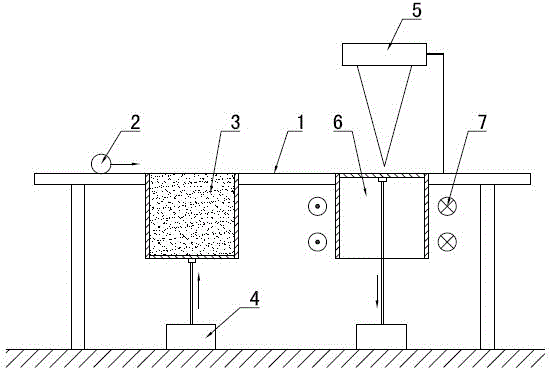
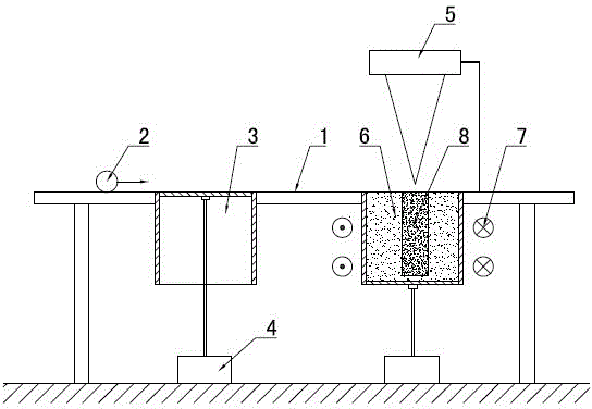
[0025] figure 1 It is the best embodiment of the laser selective sintering molding device of the rare earth permanent magnet device, and the following is combined with the attached Figure 1-2 The present invention will be further described.

[0026] Refer to attached figure 1 Disclosed is a laser selective sintering molding device for a rare earth permanent magnet device, comprising a working table 1, a powder spreading roller 2, a powder cylinder 3, a molding cylinder 6 and a laser 5. A rollable powder spreading roller 2 is provided on the upper part of the work surface 1, and a powder cylinder 3 and a forming cylinder 6 are provided on the lower part of the work surface 1. The powder cylinder 3 is filled with magnetic powder, and the bottom of the powder cylinder 3 and the forming cylinder 6 are equipped with controllable The linear lifting motor 4 of bottom plate lifting, the bottom plate of forming cylinder 6 is flush with worktable 1 in initial state. The upper part o...


PUM

PropertyMeasurementUnit
particle sizeaaaaaaaaaa

Abstract

The invention discloses a sintering molding device and method for selective laser of a rare earth permanent magnet device and relates to the field of molding processing of rare earth permanent magnetic materials. The sintering molding device is characterized by comprising a worktable (1), a powder spreading roller (2) capable of rolling is arranged on the upper portion of the worktable (1), a powder cylinder (3) and a molding cylinder (6) are arranged on the lower portion of the worktable (1), magnetic powder is accommodated in the powder cylinder (3), the lower portion of each of the powder cylinder (3) and the molding cylinder (6) is provided with a linear lifting motor (4) capable of controlling lifting of the respective bottom plate, a laser (5) is installed on the upper portion of the molding cylinder (6) in a supported manner, the molding cylinder (6) is covered with solenoidal fields (7) on the periphery, and six steps of hierarchical discretion and the like are performed by the aid of the sintering molding method for the selective laser of the rare earth permanent magnet device including establishing a CAD (computer-aided design) geometric model. By the sintering molding device and method for the selective laser of the rare earth permanent magnet device, the rare earth permanent magnetic device with high dimensional accuracy and surface smoothness can be directly manufactured, and magnetic performance is good.

Description

technical field [0001] A rare earth permanent magnet device laser selective sintering molding device and a molding method thereof relate to the field of rare earth permanent magnet material molding processing, in particular to a rare earth permanent magnet device sintering molding device and a molding method using the molding device. Background technique [0002] Rare earth permanent magnets have excellent magnetic properties and are widely used in electronics, electric machinery, medical equipment, toys, packaging, hardware machinery, aerospace and other fields. The more common ones are permanent magnet motors, speakers, magnetic separators, computer disk drives, Magnetic resonance imaging equipment instrumentation, etc. [0003] Rare earth permanent magnets are divided into sintered magnets and bonded magnets according to the manufacturing method. Sintered magnets are widely used due to their high magnetic properties, but their processing performance is poor, and they cann...

Claims


Application Information

Patent Timeline
Patent Type & Authority Applications(China)
IPC IPC(8): H01F41/02B22F3/105
Inventor 娄树普孙兆栋
Owner 爱科科技有限公司
Learn More