Near unity power factor long life low cost led lamp retrofit system and method

An LED lamp device and LED driving technology, applied in the use of semiconductor lamps, semiconductor devices of light-emitting elements, lighting and heating equipment, etc., can solve the problems of long warm-up/start-up time, large number of components, and high cost, and achieve The effect of wide working power range, small number of components and low cost

Inactive Publication Date: 2015-03-18
ALTERNATIVE LIGHTING TECH
View PDF9 Cites 10 Cited by
  • Summary
  • Abstract
  • Description
  • Claims
  • Application Information

AI Technical Summary

Problems solved by technology

[0040] The main disadvantages of sodium gas lamps are: yellow light making them suitable for outdoor applications only, long warm-up/start-up time (minutes), need for a ballast unit (certain bulb types), large size, high heat loss, easy Fragile (not resistant to mechanical shock or vibration) and more expensive to manufacture
[0177] The buck circuit topology is quite efficient (typically, Eff = 85-90%) and cost-effective. The buck circuit topology also allows the circuit to have a lower component count. It has two main disadvantages:
[0191] The disadvantages of the flyback circuit are: more expensive; more components; larger size; lower efficiency (typically 75-85%, up to 90% with expensive components); two independent grounds, requiring a complex Differential current/voltage sensing circuit and an additional opto-coupling circuit in order to control the instantaneous value of the current and vo

Method used


Image

  • Near unity power factor long life low cost led lamp retrofit system and method
  • Near unity power factor long life low cost led lamp retrofit system and method
  • Near unity power factor long life low cost led lamp retrofit system and method

Examples


Embodiment 1

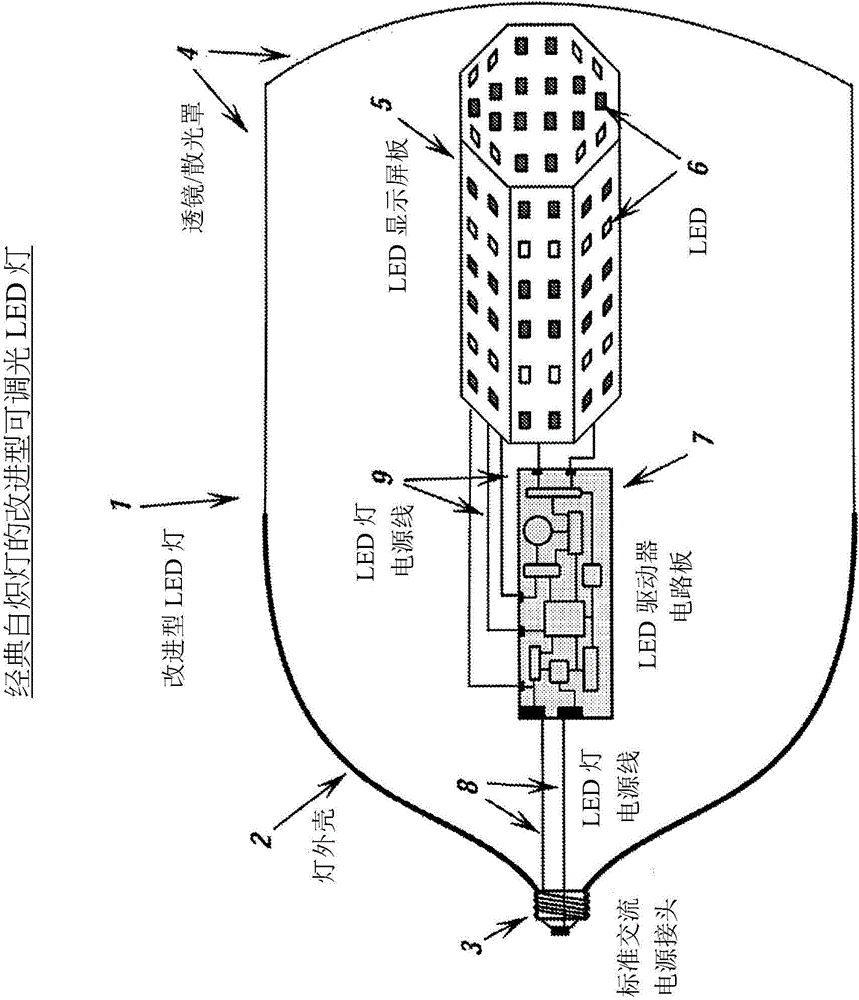
[0507] figure 1 One embodiment of a dimmable LED lamp retrofit for an incandescent lamp is shown.

[0508] As embodied herein, the retrofit LED lamp (1) includes a lamp housing (2), a standard "Edison screw" AC power connector (3), a lens / diffuser cover (4), an LED display panel (5), a Or a plurality of LEDs (6), LED driver circuit board (7), driver power line circuit system (8) and LED power line circuit system (9).

[0509] As further specifically embodied in this paper, the housing (2) of the improved LED lamp (1) is mechanically fixed to the AC power connector (3), and the connector has two electrical terminals through the AC power cord (8) and the driver circuit board (7). ) are connected. The LED driver circuit board (7) is electrically connected to the LED (6) through two or more LED power lines (9), and the LED (6) is mechanically fixed to the LED display panel (5).

[0510] Retrofit LED incandescent lamps (1) may include other wires for remote control or smart fee...

Embodiment 2

[0521] Modified Dimmable LED Lamps for Traditional Halogen Lamps

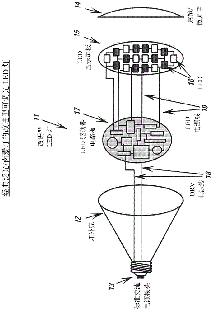
[0522] figure 2 One embodiment of a dimmable LED light retrofit of a conventional flood / halogen light is shown.

[0523] As embodied herein, the improved LED lamp (11) includes a lamp housing (12), a standard AC power connector (13), a lens / diffuser cover (14), an LED display panel (15), one or more LED (16), LED driver circuit board (17), driver power line circuit system (18) and LED power line circuit system (19).

[0524] As further embodied in this paper, the housing (12) of the improved LED lamp (11) is mechanically fixed to the AC power connector (13), and the connector has two electrical terminals through the AC power cord (18) and the driver circuit board (17). ) are connected. The LED driver circuit board (17) is electrically connected to the LED (16) through two or more LED power lines (19), and the LED (16) is mechanically fixed to the LED display panel (15).

[0525] As in other embodiments h...

Embodiment 3

[0529] Modified Dimmable LED Lamps for Traditional Fluorescent Lamps

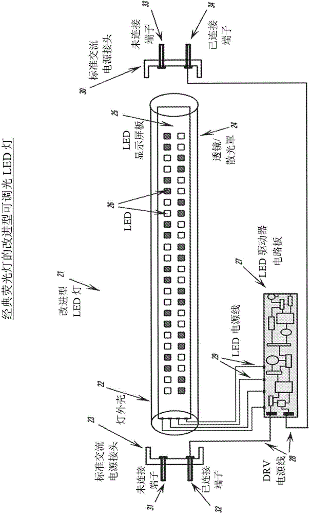
[0530] image 3 One embodiment of a dimmable LED lamp retrofit of a conventional fluorescent lamp is shown.

[0531] As embodied herein, the improved LED fluorescent lamp (21) includes a lamp housing (22), a first standard AC power connector (23) (including an unconnected terminal (31) and a connected terminal (32)), Lens / diffuser cover (24), LED display board (25), several LEDs (26), LED driver circuit board (27), driver power line circuitry (28), LED power line circuitry (29) and Two standard AC power connectors (30) (comprising an unconnected binding post (33) and a connected binding post (34)).

[0532] As further embodied herein, in this particular embodiment, the housing (22) and lens / diffuser (24) can be presented as a single glass or plastic tube that closely resembles the shape and dimensions of a conventional fluorescent tube. Possibly close for easy tube replacement in standard fixtures. In...


PUM

PropertyMeasurementUnit
Power lossaaaaaaaaaa

Abstract

Disclosed are various embodiments of low cost high quality LED (Light Emitting Diode) retrofit lamp devices capable of operating in a wide range of power and to supersede conventional lighting devices such as incandescent, halogen, sodium or fluorescent lamps. The disclosed embodiments include various LED lamp retrofit apparatuses that maximize the electro-mechanical-optical compatibility of seven interactive systems, such as: LEDs, LED Panel, Supply Adaptor, Housing, Lens/diffuser Shield, In/Out Electrical Wiring an LED driver. LED lamp retrofit apparatuses include incandescent, halogen, fluorescent, and sodium lamps. Drivers for such LED retrofit lamps include alone or in combination is double stage boost—isolated flyback, single stage boost, no opto-coupler isolated flyback, single stage single ground flyback, single stage constant off time buck-boost, single stage single ground self-supply buck-boost, pseudo double stage boost-isolated flyback, pseudo double stage boost—non isolated flyback, pseudo double stage boost—COT buck-boost, pseudo double stage boost—SG buck-boost, series circuit monolithic, parallel circuit monolithic, single cell anode loaded voltage controlled limited current switch (VCLCsw), single cell cathode loaded voltage controlled limited current switch (VCLCsw), overall feedback series monolithic circuit, overall feedback parallel monolithic circuit, monolithic multi stripes, high reliability series monolithic circuit, minimum parts series monolithic circuit, minimum parts parallel monolithic circuit, 120 Vac series monolithic circuit, simplified series monolithic circuit, simplified parallel monolithic circuit, monolithic diodes source feedback parallel circuit, operational amplifier (OPAM) monolithic parallel circuit, diodes gate feedback monolithic parallel circuit, resistor gate feedback monolithic parallel circuit, according to one embodiment, totem pole feedback monolithic parallel circuit, monolithic 8 Pin DC chip, and monolithic 8 Pin AC chip.

Description

[0001] Cross References to Related Applications [0002] This application claims U.S. Provisional Patent Application No. 61 / 576,604, filed December 16, 2011 (patent titled "NEAR UNITY POWER FACTOR LONG LIFE LOW COST LED LAMP RETROFIT SYSTEM AND METHOD"), filed October 5, 2012 U.S. Provisional Patent Application No. 61 / 710,286, entitled "NEAR UNITY POWER FACTOR LONG LIFE LOW COST LED LAMP RETROFIT SYSTEM AND METHOD," which is hereby incorporated by reference in its entirety. technical field [0003] Various embodiments disclosed herein relate to low-cost, high-quality retrofit LED (Light Emitting Diode) light fixtures that operate over a wide range of wattages and can replace traditional lighting fixtures such as incandescent, halogen, sodium, or fluorescent lights. [0004] More specifically, various embodiments disclosed herein relate to an LED lamp retrofit device that maximizes electrical, mechanical, and optical compatibility of seven interactive systems, such as: LED, LED...

Claims


Application Information

Patent Timeline
IPC IPC(8): H05B33/08H05B44/00
CPCH05B33/0818H05B33/0812H05B33/0887H05B33/0827H05B33/0815F21K9/135H05B33/083Y02B20/383H05B33/089H05B33/0824Y02B20/386F21K9/232H05B45/50H05B45/395H05B45/48H05B45/44H05B45/382H05B45/38H05B45/355Y02B20/30H05B45/385H05B45/3725H05B45/3578H05B45/3574H05B45/59H05B45/46
Inventor 本亚明·阿卡特里内依
Owner ALTERNATIVE LIGHTING TECH
Why Eureka
Try Eureka