Flue gas demisting device and method manufacturing flue gas demisting device

A defogging device and flue gas technology, applied in separation methods, chemical instruments and methods, dispersed particle separation, etc., can solve problems such as deformation of defogging elements, design of helical combs, cumbersome processing, manual welding, etc., to strengthen the fixation. , The stable effect of the defogging device

Active Publication Date: 2015-03-25
DEMISTER SHANGHAI ENVIRONMENTAL TECH
View PDF14 Cites 1 Cited by
  • Summary
  • Abstract
  • Description
  • Claims
  • Application Information

AI Technical Summary

Problems solved by technology

The main disadvantages of this method of connecting the defogging element and the sealing plate through the helical tooth comb 04 are: first, the thickness of the helical tooth comb is limited (usually 6-10mm), the end of the demisting element and the helical teeth The contact surface of the comb is very small, and the defogging element may have the risk of escaping after operation; secondly, some defogging elements and the comb must be manually welded, and the structural stability of the imitation arc-shaped module depends on the defogging of the module. The proportion and quantity of manual welding between components and combs; third, the design and processing of helical tooth combs are cumbersome, and the distance between two adjacent grooves of the helical tooth comb, the angle between the tooth groove and the strip plate (θ ) is not fixed, and the reason why it is not fixed is that these two design parameters are affected by variables such as the spacing S of the defogging element itself, the position of the special-shaped module in the circular tower, and the inclination angle of the defogging element.
In the actual project, the special-shaped modules are covered around the absorption tower, and the spaci

Method used


Image

  • Flue gas demisting device and method manufacturing flue gas demisting device
  • Flue gas demisting device and method manufacturing flue gas demisting device
  • Flue gas demisting device and method manufacturing flue gas demisting device

Examples


Embodiment 1

[0108] Example 1: Demister element holder

[0109] Such as Figure 11 As shown, this embodiment shows a demister element clamping piece 121 of a preferred embodiment of the present invention, which is used for fixing the demisting element. The clamping piece 121 includes a clamping part 1211, and the clamping part 1211 is set as It can be tightly matched with the side edge of the defogging element in a clamping manner. The clamping portion 1211 includes a first clamping flap 12111 and a second clamping flap 12112 .

[0110]The first clamping flap 12111 and the second clamping flap 12112 are respectively provided with first grooves 121111, and the first grooves 121111 are set to be able to match the first flange 011 of the side edge of the defogging element work close with. The first groove on the first clamping flap 12111 and the first groove on the second clamping flap 12112 together form an accommodating space for accommodating the first flange 011 on the side edge of the...

Embodiment 2

[0118] Embodiment 2: Demisting device

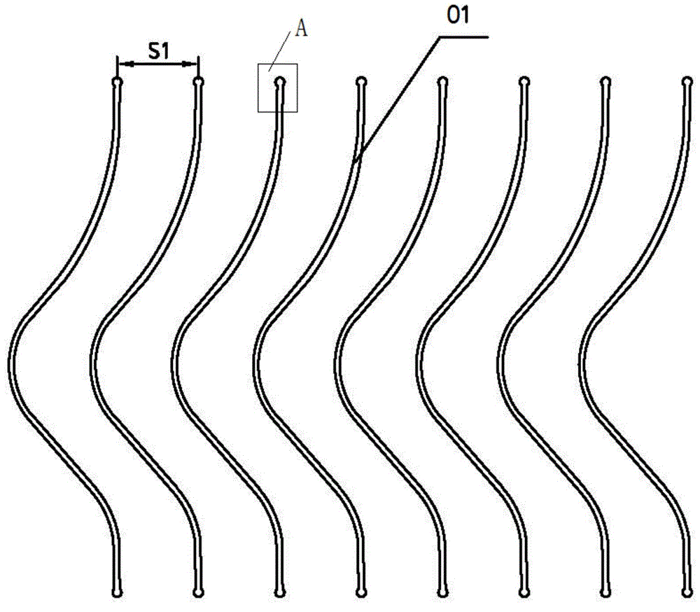
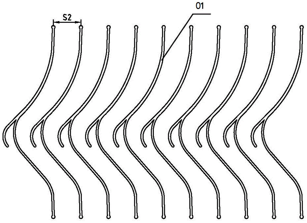
[0119] This embodiment is a preferred flue gas demister device 1 of the present invention, such as Figure 17 As shown, it includes a defogging assembly and a limiting assembly for fixing the defogging assembly. The defogging assembly includes a plurality of defogging elements 01. In this embodiment, the defogging elements 01 are corrugated plates. The limiting assembly includes a plurality of first A limiting element 121 and a plurality of second limiting elements 122. In this embodiment, the first limiting element 121 is the clamping member in Embodiment 1, and the second limiting element 122 is a connecting strip, and the connecting strip is in the shape of a strip Plastic plates. When the limiting assembly is used to fix the defogging assembly, the defogging element 01 is connected to the second limiting element 122 through the first limiting element 121, and one first limiting element 121 is correspondingly connected to one defoggi...

Embodiment 3

[0129] Embodiment 3 Tubular Roof Mist Eliminator

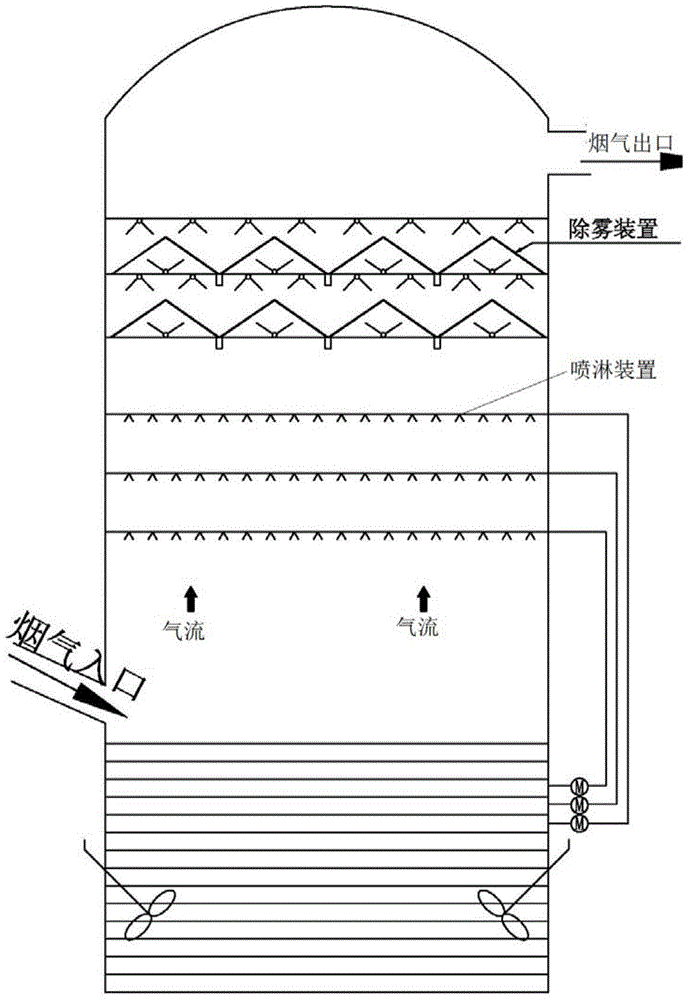
[0130] This example shows a preferred embodiment according to the present invention, which is a tubular roof mist eliminator (pipe roof mist eliminator), see Figure 23 , 24 , a tubular roof mist eliminator is configured in a circular absorption tower according to the design method of no blind zone coverage. The tubular roof mist eliminator includes a tubular roof mist eliminator 60, a first-stage roof mist eliminator 70, a second-stage roof mist eliminator 80 and a multi-layer flushing system 90, which is used for airflow flowing from bottom to top Separation of mist droplets in the airflow.

[0131] In the tubular roof demister, the tubular demister, the first-stage roof demister 70 and the first-floor flushing system (from bottom to top) are collectively installed on the lower support beam 17; the second-stage roof demister The fogger and the rest of the three-layer flushing system are collectively installed on the upper...


PUM


Abstract

The utility model discloses a flue gas mist removal device. The flue gas mist removal device comprises a mist removal component and a limit component for fixing the mist removal component, wherein the mist removal component comprises a plurality of mist removal elements, and the limit component comprises a plurality of first limit elements and one or a plurality of second limit elements; when the limit component is used for fixing the mist removal component, the mist removal elements are connected onto the second limit elements through the first limit elements, one first limit element is correspondingly connected with one mist removal element, and a plurality of first limit elements are connected onto one second limit element; the utility model further discloses a manufacturing method for the flue gas mist removal device and a mist removal element clamping piece. According to the utility model, the distances among the mist removal elements can be arranged according to the optimal design, demister standard modules and simulation circular arc-shaped modules can be manufactured easily, the structural stability of the demister modules can be improved, and the technical problems of cumbersome production of the simulation circular arc-shaped roof mist removal modules and the limitation on distance among the mist removal element can be solved.

Description

technical field [0001] The invention relates to gas-liquid separation technology and belongs to the field of flue gas desulfurization and environmental protection, in particular to a demisting device and a manufacturing method thereof. Background technique [0002] In the exhaust gas after boiler combustion, especially in the flue gas of coal-fired thermal power plants, there are a large amount of SO2, NO and other exhaust gases, which are highly corrosive when exposed to water. In order to avoid environmental pollution, they need to be removed. Usually, in The harmful gas is removed by spraying in the flue gas desulfurization absorption tower. Liquid droplets and / or particles remain in the washed flue gas. The function of the mist eliminator (mist removal device) is to intercept the mist droplets and / or particles in the clean flue gas after desulfurization and washing in this highly corrosive environment. / or particulate matter, usually these droplets contain 8 to 15% gyp...

Claims


Application Information

Patent Timeline
IPC IPC(8): B01D45/08B01D45/04
CPCB01D45/04B01D45/08
Inventor 丁俊程子剑夏亮徐成宏张爱丰马骥君
Owner DEMISTER SHANGHAI ENVIRONMENTAL TECH
Why Eureka
Try Eureka