Air purifier

An air purifier and space technology, applied in chemical instruments and methods, gas treatment, semi-permeable membrane separation, etc., can solve the problems of non-adjustable movement direction, low removal efficiency of particles and impurity gas molecules, slow movement speed, etc., to achieve The effect of improving overall performance and remarkable purification effect

Active Publication Date: 2015-03-25
伟复环保科技(北京)有限公司
View PDF5 Cites 17 Cited by
  • Summary
  • Abstract
  • Description
  • Claims
  • Application Information

AI Technical Summary

Problems solved by technology

[0002] It is pointed out in related technologies that droplets of different particle sizes in wet dust removal have higher removal efficiency for pollutants of different particle sizes, that is to say, each particle size of pollutants corresponds to an optimal particle size However, in the purification method in the related art, the droplets used for purification cannot produce a specific particle size distribution pattern, and the particle size distribution range cannot be precisely controlled as required. For example, 500 microns to 1000 microns are often used in the related art The liquid droplets of about micron are used for purification, the particle size distribution range of the droplets is small, and the removal efficiency of particulate matter and impurity gas molecules below PM10 is low
In addition, in the purification method in the related art, the liquid film used for purification is only a two-dimensional liquid film, the spatial distribution pattern is fixed, the movement speed is slow, and the movement direction cannot be adjusted, so that it cannot fully interact with the pollutants, and the purification effect not good
In summary, the wet purifiers in the related art cannot take into account the removal effect of larger particle pollutants above 10 microns and respiratory dust and impurity gases below 10 microns. In addition, for some particles that are not easily soluble in the purification liquid Pollutants, droplet pollutants, gas pollutants, etc., the purification effect is poor

Method used


Image

  • Air purifier
  • Air purifier
  • Air purifier

Examples


Embodiment 1

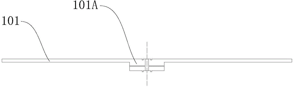
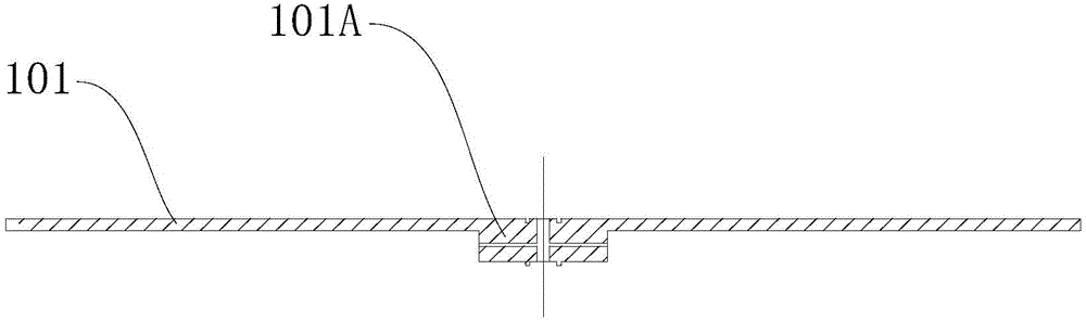
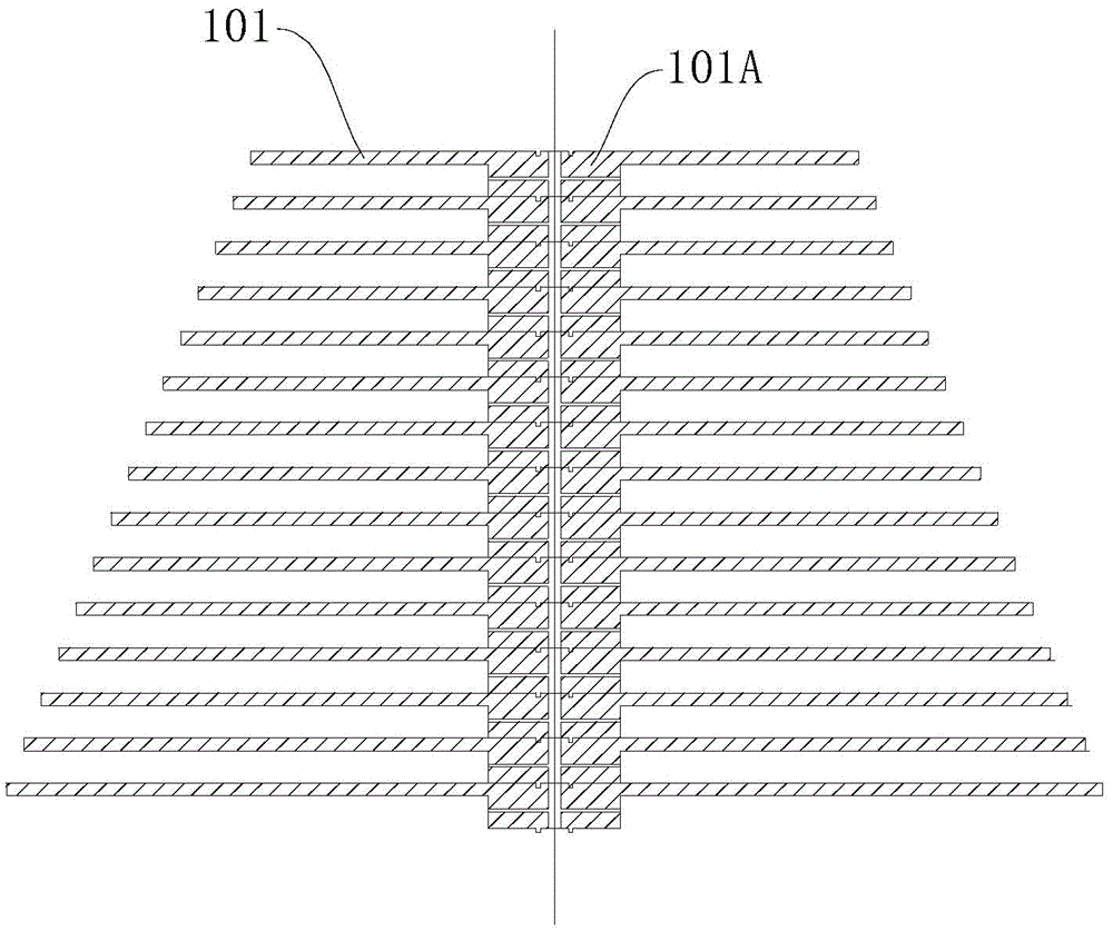
[0073] Such as Figure 1-Figure 4 As shown, the liquid rejection assembly includes a rotating shaft 101A and at least one liquid rejection disk 101, at least one liquid rejection disk 101 is detachably connected to the rotation shaft 101A, wherein at least one liquid rejection disk 101 is rotatable around the central axis of the rotation shaft 101A, and the rotation axis is the central axis of the rotating shaft 101A. refer to image 3 The rotating shaft 101A can be a rotating shaft 101A extending along a straight line, and can also be a rotating shaft 101A extending along a curve. The rotating axis of the rotating shaft 101A is the central axis of the rotating shaft 101A, and the central axis of the rotating shaft 101A is the rotating axis of the liquid rejection assembly.

[0074] Among them, refer to image 3 One or more liquid throwing disks 101 can be directly installed on the rotating shaft 101A, and each liquid throwing disk 101 can be driven by the rotating shaft 101...

Embodiment 2

[0085] Such as Figure 5-Figure 8 As shown, the liquid rejection assembly includes a rotating shaft 102A and at least one liquid rejection brush 102, each liquid rejection brush 102 includes a plurality of bristles 1021, at least one liquid rejection brush 102 is detachably connected to the rotating shaft 102A, wherein at least one liquid rejection brush 102 is rotatable around the central axis of the rotating shaft 102A, and the rotating axis is the central axis of the rotating shaft 102A. refer to Figure 7 The rotating shaft 102A can be a rotating shaft 102A extending along a straight line, and can also be a rotating shaft 102A extending along a curve. The rotating axis of the rotating shaft 102A is the central axis of the rotating shaft 102A, and the central axis of the rotating shaft 102A is the rotating axis of the liquid rejection assembly.

[0086] Among them, such as Figure 5-Figure 8 As shown, one or more liquid rejection brushes 102 can be directly installed on t...

Embodiment 3

[0097] Such as Figure 9 As shown, the rotating shaft 103A is formed in a hollow tubular shape, and a plurality of liquid holes 1031 are formed on the rotating shaft 103A so that the liquid can be thrown out from the plurality of liquid holes 1031 . Specifically, the rotating shaft 103A can be configured as a hollow pipeline, and the pipe wall of the rotating shaft 103A can be formed with a penetrating liquid hole 1031, and the rotating shaft 103A can pass liquid into the rotating shaft 103A during the rotation process, and the rotating shaft 103A can , the liquid in the rotating shaft 103A can be thrown out from the liquid hole 1031 on the tube wall, so that a three-dimensional droplet field 210A and / or a three-dimensional liquid film field 210B can be generated. Wherein, the predetermined distribution of the three-dimensional droplet field 210A and / or the three-dimensional liquid film field 210B can be adjusted by adjusting the rotation speed of the rotating shaft 103A and t...


PUM

PropertyMeasurementUnit
particle diameteraaaaaaaaaa

Abstract

The invention discloses an air purifier. The air purifier comprises a shell, a liquid storage device and a liquid throwing-off device, wherein a liquid throwing-off space is formed inside the shell, an air inlet communicated with the liquid throwing-off space is formed on the shell, the liquid storage device is arranged in the shell, the liquid throwing-off device is arranged in the liquid throwing-off space and comprises a liquid throwing-off assembly, the liquid throwing-off assembly is constructed to convert liquid supplying to the liquid throwing-off assembly into a three-dimensional liquid field formed in a three-dimensional space where the liquid throwing-off assembly is arranged, the three-dimensional liquid field comprises at least one of a three-dimensional liquid drop field and a three-dimensional liquid membrane field, the three-dimensional liquid drop field is composed of liquid drops with one or more particle sizes in a preset distributing mode, the three-dimensional liquid membrane field is composed of a liquid membrane formed on the liquid throwing-off assembly, and the liquid throwing-off device is used for converting liquid supplying to the liquid throwing-off device from the liquid storage device into the three-dimensional liquid membrane field and/or the three-dimensional liquid drop field to adsorb impurity pollutants in the air and deliver the impurity pollutants out from an air outlet, wherein the impurity pollutants in the air enter the liquid throwing-off space through the air inlet. According to the air purifier, the purifying effect is remarkable.

Description

technical field [0001] The invention relates to the field of purification equipment, in particular to an air purifier. Background technique [0002] It is pointed out in related technologies that droplets of different particle sizes in wet dust removal have higher removal efficiency for pollutants of different particle sizes, that is to say, each particle size of pollutants corresponds to an optimal particle size However, in the purification method in the related art, the droplets used for purification cannot produce a specific particle size distribution pattern, and the particle size distribution range cannot be precisely controlled as required. For example, 500 microns to 1000 microns are often used in the related art The liquid droplets of about micron are used for purification, the particle size distribution range of the droplets is small, and the removal efficiency of particulate matter and impurity gas molecules below PM10 is low. In addition, in the purification meth...

Claims


Application Information

Patent Timeline
Patent Type & Authority Applications(China)
IPC IPC(8): B01D47/06
CPCB01D47/06B01D2258/06B01D61/00
Inventor 秦毅赵龙杨中宇李日宗商志刚陈梦
Owner 伟复环保科技(北京)有限公司
Why Eureka
Try Eureka