
Atomizing device for space spray coating

A technology of atomization device and space, applied in the direction of spray device, spray device, etc., can solve the problems of hollow, split beam, uneven atomization surface, etc., achieve strong flexibility, expand the scope of use, and excellent uniform atomization effect. Effect

Inactive Publication Date: 2015-03-25
CHINA ACADEMY OF SPACE TECHNOLOGY
View PDF6 Cites 15 Cited by
  • Summary
  • Abstract
  • Description
  • Claims
  • Application Information

AI Technical Summary

Problems solved by technology

The configuration of the conical spiral nozzle is a gradually smaller multi-turn helical structure. The angle (helix angle) between the streamline of the spray surface of the cone of different layers and the axis of the spray component is different, and the angle decreases layer by layer. Concentric circles with the same spacing can be formed. The atomization surface is generally composed of 2 to 4 interconnected concentric atomization circles. The conical spiral nozzle is easy to obtain a larger spray diffusion angle, but the atomization surface is not uniform. The phenomenon of hollow and beam splitting is more obvious

Method used


Image

  • Atomizing device for space spray coating
  • Atomizing device for space spray coating

Examples


Embodiment Construction

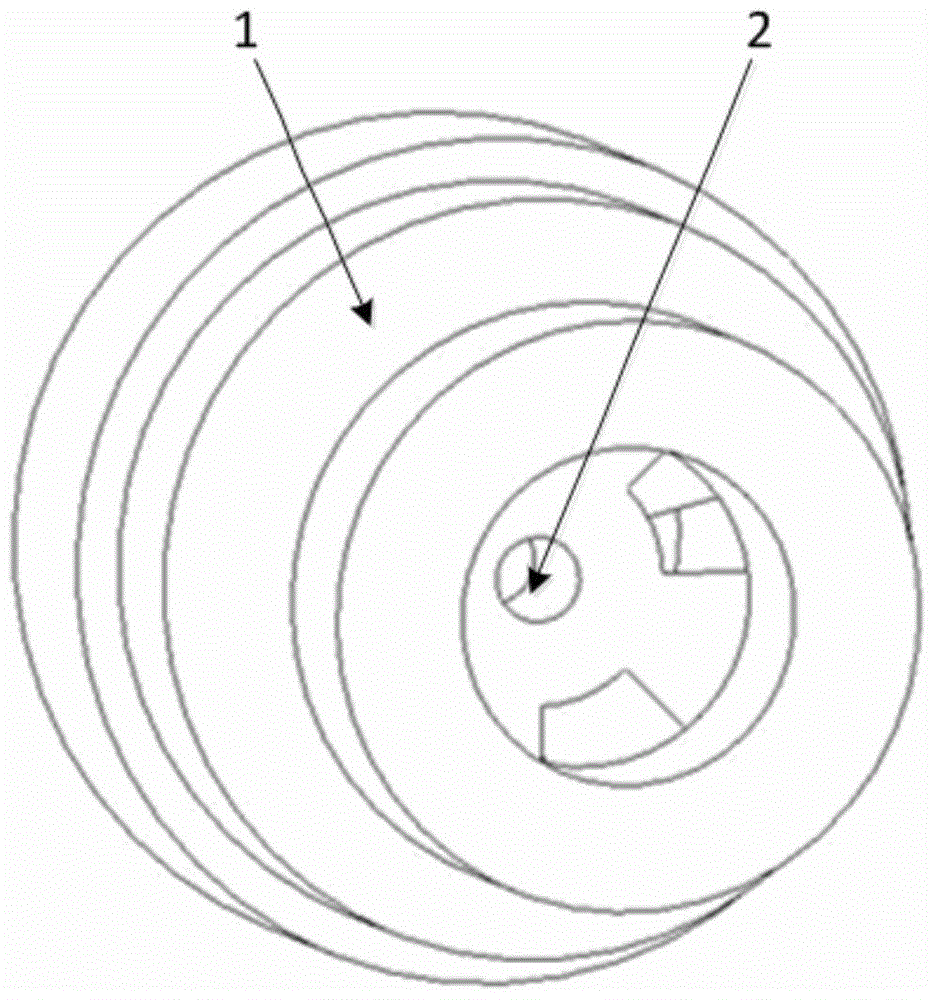
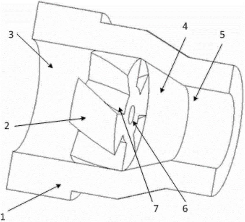
[0021] Such as figure 1 , figure 2 Shown is the structural composition diagram of the nozzle device of the present invention, one end of the nozzle device is the liquid inlet side, and the other end is the liquid outlet side, including: swirl chamber 1 and swirl core 2, swirl chamber 1 mainly consists of three parts Composition: Inlet section 3, Convergence section 4, Exit section 5. The swirl core 2 mainly includes a central hole flow channel 6 and four spiral guide flow channels 7 equidistant from the periphery. The swirl core 2 is installed on the innermost side of the inlet section of the swirl chamber 1 (near the converging section 4), and the swirl chamber 1 and the swirl core 2 are fixed by interference fit.

[0022] The inlet section 3 and the outlet section 5 of the swirl chamber 1 are cylindrical, and the converging section 4 is conical, with circular cross-sections. The main function of the swirl chamber 1 is to convert the pressure energy of the liquid to be at...


PUM


Abstract

An atomizing device for space spray coating comprises a rotational flow cavity (1) and a rotational flow chip (2). The rotational flow cavity (1) comprises an inlet section (3), a convergence section (4) and an outlet section (5). The body of the rotational flow chip (2) is cylindrical. A central hole passageway (6) and four spiral guide passageways (7) arranged on the periphery of the central hole passageway (6) at equal intervals are arranged on the cylindrical rotational flow chip (2). The rotational flow chip (2) is arranged on the innermost side, namely, the position close to the convergence section, of the inlet section in the rotational flow cavity (1). The rotational flow cavity (1) and the rotational flow chip (2) are connected and fixed through interference fit.

Description

technical field [0001] The invention relates to a nozzle atomization device for space liquid spraying, which is suitable for spraying liquid materials on starboard equipment on orbit, and realizes performance improvement on starboard equipment. Background technique [0002] With the development of satellite in-orbit service technology, on-orbit assembly and on-orbit construction will become a reality. On-orbit assembly and on-orbit construction of the spacecraft have temperature control requirements for the star surface. At present, all thermal control coatings for satellite equipment are developed, sprayed, and cured on the ground according to their film thickness, radiation / reflection characteristics, and adaptability to vacuum environments, and then the equipment is assembled and launched into orbit. For spacecraft assembled and built on orbit, thermal control coatings need to be sprayed on the surface of the star in orbit. In addition to on-orbit assembly and on-orbit ...

Claims


Application Information

Patent Timeline
IPC IPC(8): B05B1/34
CPCB05B1/3405
Inventor 李志陈维春蒙波黄剑斌孙玉成尹建凤韩旭
Owner CHINA ACADEMY OF SPACE TECHNOLOGY
Learn More