A non-contact energy transfer device for rotary ultrasonic machining

A rotary ultrasonic and energy transmission technology, applied in positioning devices, metal processing equipment, fluids using vibration, etc., can solve the problems of reducing the automation level of processing efficiency, large transformation costs and capital investment, and adverse processing safety. Preparation time, increased automation level, improved machining efficiency and effect of automation level

Active Publication Date: 2017-01-11
DALIAN UNIV OF TECH
View PDF7 Cites 1 Cited by
  • Summary
  • Abstract
  • Description
  • Claims
  • Application Information

AI Technical Summary

Problems solved by technology

This frequent manual tool change process reduces the processing efficiency and the automation level of production; if you want to realize the automatic tool change function, you need to carry out a lot of transformation on the machine tool itself or the tool change mechanism, and the transformation cost and capital investment are huge; In addition, The introduction of human factors such as manual tool change and the relatively closed energy transmission space are not conducive to the safety of the processing process.
The existing non-contact energy transmission device also has disadvantages such as poor adaptability to different machine tools and different tool holder structures, and inconvenient installation and debugging.

Method used


Image

  • A non-contact energy transfer device for rotary ultrasonic machining
  • A non-contact energy transfer device for rotary ultrasonic machining
  • A non-contact energy transfer device for rotary ultrasonic machining

Examples


Embodiment 1

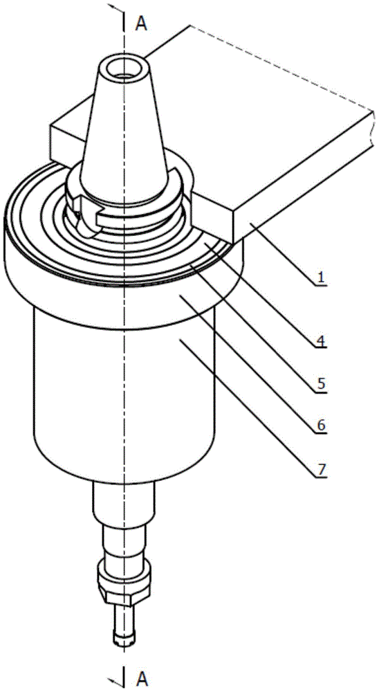
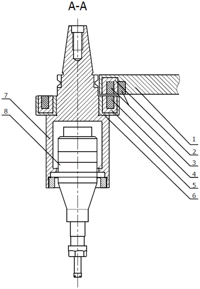
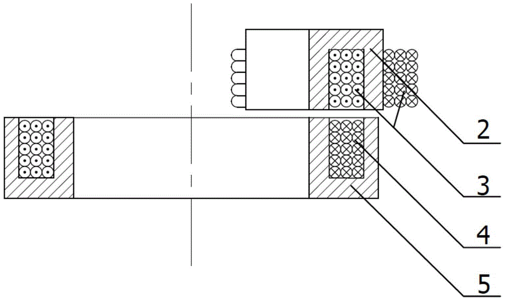
[0041] Such as figure 1 , 2 , 3, and 4 are schematic diagrams of Embodiment 1 of the axially open non-contact energy transmission device of the present invention. Among them, in addition to the adjustment mechanism and the rotating ultrasonic handle, the openness of the core non-contact energy transmission device is mainly reflected in the magnetic core structure and winding method: in this embodiment, an axially open non-contact energy transmission device is used . In terms of magnetic core structure, the fixed-end magnetic core 2 and the rotating-end magnetic core 5 adopt partial and complete pot-shaped magnetic cores respectively. The two are coaxial and arranged with a small gap between the axes. The effective area A passing through the lines of magnetic field e In the same way, an open magnetic field circuit is formed; in the winding method, the fixed-end coil 3 is wound on the outer wall of the fixed-end magnetic core 3, and the rotating-end coil 4 is wound in the gr...

Embodiment 2

[0043] Such as Figure 5 , 6 , 7, and 8 are schematic diagrams of Embodiment 2 of the radially open non-contact energy transmission device of the present invention, which are the same as figure 1 , 2 , 3, and 4 show the similarities between the adjustment mechanism and the rotating ultrasonic knife handle in Embodiment 1, so the description will not be repeated, and only the differences will be described.

[0044] In the second embodiment, a radially open non-contact energy transmission device is used. Its openness is reflected in: in the magnetic core structure, the fixed-end magnetic core 2 and the rotating-end magnetic core 5 adopt part and the whole slotted annular magnetic core respectively, and the two are coaxial and arranged with small radial gaps. It is the same as the effective area Ae of the rotating end magnetic core 5 through the magnetic induction line, forming an open magnetic field circuit; in the winding mode, the fixed end coil 3 is wound on the outer wal...


PUM


Abstract

The invention discloses a non-contact energy transmission device for rotary ultrasonic processing. The non-contact energy transmission device comprises a fixed end and a rotating end. The opposite positions of the fixed end and the rotating end are each of an axial opened type or a radial opened type. When the opposite positions of the fixed end and the rotating end are of the axial opened type, a magnetic core of the fixed end is a part cut from a tank type magnetic core, and the central angle of the part cut from the tank type magnetic core is smaller than or equal to 180 degrees; a magnetic core of the rotating end is a complete tank type magnetic core. When the opposite positions of the fixed end and the rotating end are of the radial opened type, the magnetic core of the fixed end is a part cut from an annular inner groove magnetic core, and the central angle of the part cut from the annular inner groove magnetic core is smaller than or equal to 180 degrees; a magnetic core of the rotating end is a complete annular outer groove magnetic core. By means of the non-contact energy transmission device, the processing efficiency and automation level can be improved, the improvement cost and capital investment can be saved, the safety and applicability of an ultrasonic processing device can be improved, and the installation performance and adjustment performance are good.

Description

technical field [0001] The invention belongs to the technical equipment field of rotary ultrasonic processing, and in particular relates to a non-contact energy transmission device for rotary ultrasonic processing. Background technique [0002] Rotary ultrasonic machining technology is a processing method based on traditional rotary machining technology and combined with ultrasonic vibration to achieve material removal. Rotary ultrasonic machining can effectively reduce cutting force, reduce tool wear, and improve material removal rate, especially for difficult-to-machine materials. Therefore, rotary ultrasonic machining technology is widely used in the processing of hard and brittle materials such as ceramics and glass, as well as difficult-to-machine materials such as fiber-reinforced composite materials. [0003] Rotary ultrasonic machining methods mainly include: rotary ultrasonic milling, rotary ultrasonic grinding, rotary ultrasonic turning, rotary ultrasonic drilling...

Claims


Application Information

Patent Timeline
Patent Type & Authority Patents(China)
IPC IPC(8): B23B31/02
CPCB06B3/00B23Q3/12
Inventor 董志刚康仁科王毅丹周平孙雷刘津廷
Owner DALIAN UNIV OF TECH
Why Eureka
Try Eureka