Rapid clamping and drilling mould for machining of side hole of round steel

A round steel, fast technology, applied in the direction of the drilling mold used for the workpiece, etc., can solve the problems of difficult to ensure the concentricity of the hole, prolong the processing time of parts, exhaust gas and other problems, and achieve the effect of improving drilling efficiency and quality

Inactive Publication Date: 2015-03-25
TIANJIN ANSHUNCHENG METAL PROD
View PDF7 Cites 10 Cited by
  • Summary
  • Abstract
  • Description
  • Claims
  • Application Information

AI Technical Summary

Problems solved by technology

[0002] At present, in the prior art, the drilling of round steel is generally marked first, and after the specific location of the drilling is determined, it is clamped on the workbench to perform the drilling process; there are many problems in this traditional processing method, such as The concentricity of the hole is difficult to be guaranteed. When drilling, it is easy to be deflected due to inaccurate clamping or alignment. The drilling with a small amount of deflection can still be used after correction, but the processing time of the part is greatly prolonged. At the same time, it also increases the manufact

Method used


Image

  • Rapid clamping and drilling mould for machining of side hole of round steel
  • Rapid clamping and drilling mould for machining of side hole of round steel
  • Rapid clamping and drilling mould for machining of side hole of round steel

Examples


Example Embodiment

[0012] In order to further understand the content, features and effects of the present invention, the following embodiments are given as examples, and detailed descriptions are as follows with accompanying drawings:

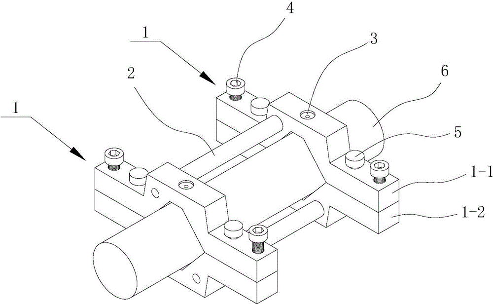
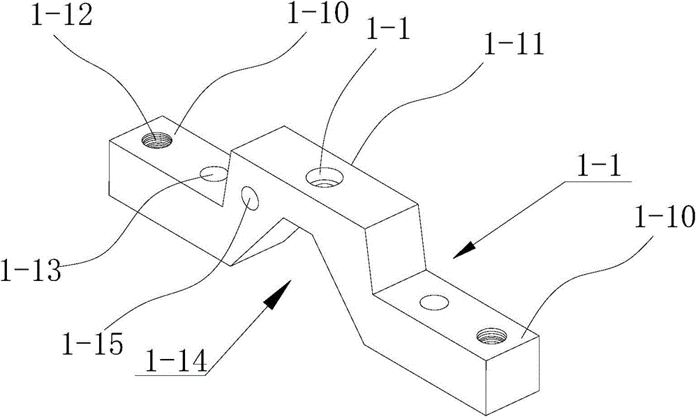
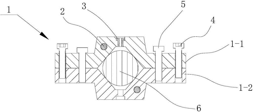
[0013] See Figure 1 to Figure 3 , A quick clamping drilling mold for processing round steel side holes, comprising two clamping components 1 for clamping round steel, a positioning rod 2 is inserted between the two clamping components, positioning rod The center distance between adjacent holes can be ensured. Each of the above-mentioned clamping components is provided with a drill sleeve 3; the above-mentioned clamping component 1 includes an upper clamping body 1-1 and a lower clamping body 1-2, The upper clamping body includes a connecting portion 1-10 and a clamping portion 1-11, wherein the connecting portion is provided with a connecting screw hole 1-12 and a positioning pin hole 1-13, and the clamping portion 1-11 There are isosceles trapezoidal openings 1-1...


PUM


Abstract

The invention relates to a rapid clamping and drilling mould for machining of a side hole of round steel. The rapid clamping and drilling mould for machining of the side hole of the round steel comprises two clamping assemblies and a positioning rod, wherein the two clamping assemblies are used for clamping the round steel, each clamping assembly comprises an upper clamping body and a lower clamping body, each upper clamping body comprises a connecting part and a clamping part, a connecting screw hole and a positioning pin hole are formed in each connecting part, an isosceles-trapezoid-shaped opening is formed in each clamping part, a through drill hole is formed in the top of each opening, and a drill jig sleeve is arranged in each drill hole; the upper clamping body and the lower clamping body of each clamping assembly are of the same structure and are combined together, the screw hole and the positioning pin hole of each upper clamping body correspond to a screw hole and a positioning pin hole of the corresponding lower clamping body, connecting bolts are arranged in the screw holes in a screwed mode, and positioning pins are inserted in the positioning pin holes; a round steel clamping cavity is formed after the upper clamping bodies and the lower clamping bodies are combined together. According to the rapid clamping and drilling mould for machining of the side hole of the round steel, the round steel is clamped in a one-time mode through the drilling mold, machining of the whole hole is achieved, drilling efficiency and drilling quality are improved, and the coaxiality of drilled holes and the distances between adjacent holes are guaranteed; deflected holes and eccentric holes are avoided, and product quality is improved.

Description

Technical field [0001] The invention belongs to the technical field of machining, and particularly relates to a quick clamping drilling tool for processing round steel side holes. Background technique [0002] At present, in the prior art, the drilling of round steel is generally scribed first, and after the specific location of the drilling is determined, it is clamped on the worktable for the drilling process; this traditional processing method has many problems, such as The concentricity of the hole is difficult to guarantee. It is easy to deviate due to inaccurate clamping or alignment during drilling. Drilling with a small amount of deflection can continue to be used through correction, but it greatly extends the processing time of the parts. At the same time, it also increases the manufacturing cost; for drilling holes with large deflection, only exhaust gas can be used, resulting in waste of resources. [0003] For round steel with a large diameter, drill through holes in t...

Claims


Application Information

Patent Timeline
IPC IPC(8): B23B47/28
CPCB23B47/281B23B2247/12
Inventor 崔建晨
Owner TIANJIN ANSHUNCHENG METAL PROD
Why Eureka
Try Eureka