A gantry type automatic fillet welding vehicle

A rack-type and automatic technology, applied in welding equipment, welding accessories, arc welding equipment, etc., can solve the problem of welding seam repair workload and plate frame correction workload, difficult to control the welding deformation of flat plate frame, and the kinetic energy of crane equipment. problems such as large interference, to achieve the effect of reducing human influence factors, stable welding process parameters, and simple structure

Inactive Publication Date: 2016-08-24
广州黄船海洋工程有限公司
View PDF5 Cites 0 Cited by
  • Summary
  • Abstract
  • Description
  • Claims
  • Application Information

AI Technical Summary

Problems solved by technology

[0002] Most of the shipbuilding enterprises still adopt the "single person, single machine, single weld" welding mode for the welding of the fillet welds of the flat panel unit components. Since the fillet welds of each profile cannot be welded simultaneously, the flat panel unit Direction, welding construction with the same technical parameters lead to different shrinkage of the weld seam, it is difficult to control the welding deformation of the flat plate frame, the quality of the weld seam is poor, the workload of weld repair and plate frame correction is large, and the work efficiency is low
At present, domestic advanced shipbuilding enterprises have introduced automatic fillet welding equipment such as "T-row welding assembly line". The crawler transmission device is arranged on the ground, and the welding machine equipment is arranged in fixed positions. Although this kind of automatic welding equipment has high welding efficiency, However, the initial investment cost is high, and it has great interference with other crane equipment and kinetic energy in the workshop, and often does not match with the hardware facilities of the workshop, so it cannot exert its maximum effect.

Method used


Image

  • A gantry type automatic fillet welding vehicle
  • A gantry type automatic fillet welding vehicle
  • A gantry type automatic fillet welding vehicle

Examples


Embodiment

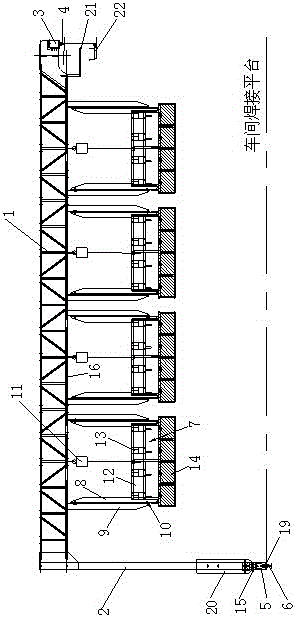
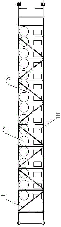
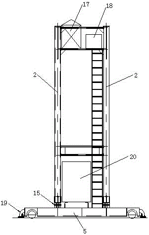
[0034] Such as Figure 1-2 As shown, the gantry type automatic fillet welding vehicle of this embodiment includes a gantry traveling mechanism, several welding trolley frame lifting mechanisms, an electrical control system, a flexible drag chain power system, a CO 2 Gas shielded welding equipment, the lifting mechanism of the welding trolley frame is suspended and arranged under the traveling mechanism of the gantry, and the CO 2 The welding host 18 of the gas shielded welding equipment is set on the gantry traveling mechanism, CO 2 The welding head 13 of the gas shielded welding equipment is set on the lifting mechanism of the welding trolley frame, and the electrical control system controls the gantry traveling mechanism, CO 2 Gas shielded welding equipment, the operation of the lifting mechanism of the welding trolley frame, the flexible drag chain power system supplies power for the electrical control system, and provides power for the CO 2 Gas shielded welding equipment...


PUM


Abstract

The invention relates to the technical field of ship structure construction, in particular to a gantry type automatic angle welding vehicle used for fillet weld welding of a plane flat rack unit element sectional material of a ship steel structure. The gantry type automatic angle welding vehicle comprises a gantry walking mechanism, a plurality of welding trolley frame lifting mechanisms, an electrical control system, a flexible drag chain power system and a CO2 gas shield welding device. The welding trolley frame lifting mechanisms are hung below the gantry walking mechanism, the electrical control system controls the gantry walking mechanism, the CO2 gas shield welding device and the welding trolley frame lifting mechanisms to operate, and the flexible drag chain power system supplies power to the electrical control system and provides a gas source needed in work by the CO2 gas shield welding device. According to the gantry type automatic angle welding vehicle, the welding quality of a fillet weld can be ensured, the labor intensity of constructors can be relieved, the welding efficiency is greatly improved, and the production cost is reduced.

Description

technical field [0001] The invention relates to the technical field of ship structure construction, in particular to a gantry-type automatic fillet welding vehicle used for welding fillet welds of single element profiles of ship steel structure plane plate frames. Background technique [0002] Most of the shipbuilding enterprises still adopt the "single person, single machine, single weld" welding mode for the welding of the fillet welds of the flat panel unit components. Since the fillet welds of each profile cannot be welded simultaneously, the flat panel unit Direction, welding construction with the same technical parameters lead to different shrinkage of the weld seam, it is difficult to control the welding deformation of the flat plate frame, the quality of the weld seam is poor, the workload of weld repair and plate frame correction is large, and the work efficiency is low. At present, domestic advanced shipbuilding enterprises have introduced automatic fillet welding ...

Claims


Application Information

Patent Timeline
Patent Type & Authority Patents(China)
IPC IPC(8): B23K9/16B23K9/12B23K9/32
CPCB23K9/12B23K9/16B23K9/32
Inventor 梁俊民何开平李华鹏李家林
Owner 广州黄船海洋工程有限公司
Why Eureka
Try Eureka