Low-noise hydraulic steering gear

A hydraulic steering gear, low-noise technology, applied in the direction of steering mechanism, fluid steering mechanism, power steering mechanism, etc., can solve the problems of complicated flow path, high noise of steering gear, and affecting the quality of steering gear, so as to reduce noise, flow speed and The effect of soft pressure changes

Inactive Publication Date: 2015-03-25
ZHENJIANG HYDRAULICS
View PDF9 Cites 8 Cited by
  • Summary
  • Abstract
  • Description
  • Claims
  • Application Information

AI Technical Summary

Problems solved by technology

[0003] As far as the applicant knows, the steering switching control of the steering gear in the prior art is very noisy
Since the interior of the steering gear involves complex mechanisms such as cycloidal pin-wheel pairs and linkage transmission, the flow path is also very complicated, and there are many possible causes of noise.
Therefore, the above-mentioned problems have not been effectively solved for a long time, and have become a technical problem, which has affected the quality of the steering gear.

Method used


Image

  • Low-noise hydraulic steering gear
  • Low-noise hydraulic steering gear
  • Low-noise hydraulic steering gear

Examples


Embodiment 1

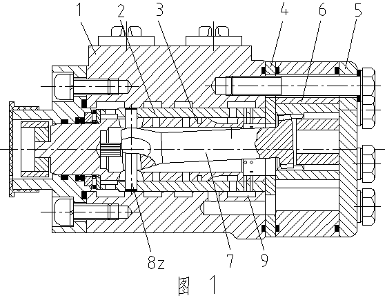
[0030] The low-noise hydraulic steering gear of this embodiment is as figure 1 As shown, its basic structure is the same as the prior art, and the right end of the valve body is equipped with a cycloidal pinwheel engagement pair 6 between the partition plate 4 and the back cover 5 . The inner hole of the valve body 1 has a valve body oil inlet ring groove 9 and is installed with an indexable valve core 3 with a flow channel through the valve sleeve 2, or in other words, the valve hole of the valve body 1 is equipped with a valve sleeve 2 and a cartridge Indexable spool 3 in the valve sleeve. The valve core 3 is equipped with a linkage shaft 7, and one end of the linkage shaft 7 is respectively connected with the valve sleeve 2 and the valve core 3 through the dial pin 8 and the elastic member to form a rotary valve flow distribution mechanism matched with the flow channel of the valve body 1. The other end of the linkage shaft 7 is connected to the cycloidal pinwheel meshing ...

Embodiment 2

[0036] The basic structure of the low-noise hydraulic steering gear of this embodiment is the same as that of Embodiment 1. The difference is the specific structure of the valve sleeve 2 and the valve core 3 .

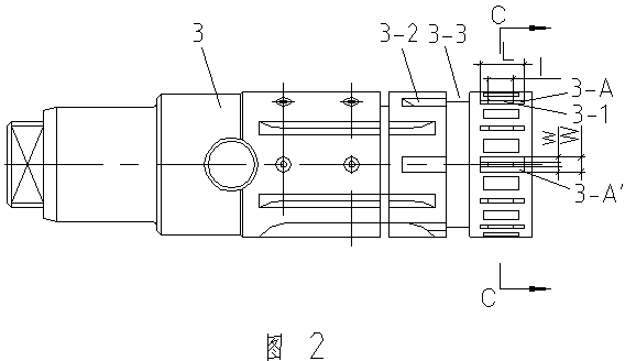
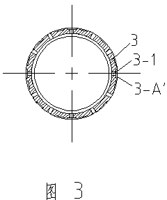
[0037] The valve sleeve 2 of the present embodiment is as Figure 4 and Figure 5 shown, see Figure 9 , Figure 9' , one end has a set with figure 1 Two rows of 12 pairs of radial valve sleeve oil return groove holes 2-1 corresponding to the right side of the valve body oil inlet ring groove 9 of the middle valve body 1 are distributed at circumferential intervals. Each valve sleeve oil return groove hole 2-1 is made of round counterbore 2-1-1 and the slot 2-1-2 at the bottom of round counterbore. The outer mouth of each pair of round counterbore 2-1-1 is shaped on the accumulator 2-1-3 of circular arc bottom. The slot 2-1-2 of the oil return groove hole 2-1 of the valve sleeve is formed with an arc bottom buffer groove 2-A whose axial extension length L is greate...


PUM


Abstract

The invention relates to a low-noise hydraulic steering gear, and belongs to the field of hydraulic technologies. The steering gear is provided with a valve body oil inlet ring groove, a valve sleeve and a valve core, valve sleeve oil return holes are formed in one end of the valve sleeve, valve sleeve oil distributing holes are formed in the middle section of the valve sleeve, and valve sleeve oil inlet holes are formed between the valve sleeve oil return holes and the valve sleeve oil distributing holes; a set of valve core oil return holes which correspond to the valve sleeve oil return holes in position and are distributed at intervals in the circumferential direction is formed in one end of the valve core, an oil distributing ring groove is formed in the position, corresponding to the valve sleeve oil inlet holes, of the valve core, and the oil distributing groove extends at intervals in the circumferential direction to form a set of communicating grooves corresponding to the valve sleeve oil distributing holes in position; buffering grooves are manufactured in the positions corresponding to at least one set of the valve sleeve oil return holes and the valve core oil return holes, and the axial extending length of the buffering grooves is larger than the circulating length of the oil return holes. Closure or communication of the oil return holes will become gentle due to the gradual transition of the intermediate state, the flow rate and the pressure of hydraulic oil change gently, and consequently noise is reduced effectively.

Description

technical field [0001] The invention relates to a steering gear, in particular to a low-noise hydraulic steering gear, and belongs to the technical field of hydraulic pressure. Background technique [0002] The hydraulic steering gear is a steering control device commonly used in construction machinery, agricultural machinery and other engineering vehicles. It is mainly composed of rotor stator meshing pair, valve body, valve core sleeve assembly and other components. Wherein, the valve core sleeve assembly is composed of a valve core and a valve sleeve, and the valve core is installed inside the valve sleeve. For further understanding of the specific structure and working principle of the steering gear, please refer to the Chinese patent document with application number 200810020802.3, which discloses that one end of the valve body of the steering gear supports an indexable valve core, and there is a valve sleeve between the valve core and the valve body , the valve body, ...

Claims


Application Information

Patent Timeline
Patent Type & Authority Applications(China)
IPC IPC(8): B62D5/08
CPCB62D5/0837
Inventor 焦文瑞潘骏秦志文沈启志杨培宣曙江邵昀张强华阮永强
Owner ZHENJIANG HYDRAULICS
Why Eureka
Try Eureka