Concrete engineering cavity die gasbag and manufacturing method thereof

A technology for concrete and second-stage concrete, which is used in marine engineering, earth-moving drilling, water conservancy engineering, etc., can solve the problems of irregular deformation of concrete grooves, non-reusable, soft asphalt running off, etc., to prevent cross-section interface dislocation , the section is neat, the effect of saving the construction period

Active Publication Date: 2015-03-25
湖南恒运建筑科技发展有限公司
View PDF4 Cites 3 Cited by
  • Summary
  • Abstract
  • Description
  • Claims
  • Application Information

AI Technical Summary

Problems solved by technology

[0002] In existing concrete structures, such as retaining dams, reservoirs, subways, culverts, sluices, tunnels and other underground and underwater projects, due to the inability to pour continuously or the deformation of the foundation settlement (earthquake), or due to temperature changes Due to thermal expansion and contraction of concrete components caused by thermal expansion and contraction, deformation joints and construction joints are often deliberately left during pouring. These gaps must take anti-leakage measures to prevent external water or groundwater from leaking into the structural space. The current common practice is A concrete groove is set between the first-stage concrete and the second-stage concrete, and soft asphalt and copper sheets or rubber waterstops are arranged in the groove. However, this method requires prefabricated concrete grooves. In order to make the concrete grooves and the second-stage concrete tightly combined, It is necessary to chisel rough treatment on the 3 sides of the concrete trough, which will prolong the construction period and increase labor. At the same time, since the length (height) of each concrete trough is generally only 50-100cm, the deformation gap must be formed by connecting multiple concrete troughs, so it will The generation of multiple transverse gaps and the irregular deformation of multiple concrete tanks will cause the leakage of soft asphalt in the subsequent pouring, and it is difficult to clean up; and the technology of using channel steel instead of concrete tanks in patent application No. 2014100489253, although Compared with the original construction method, it can save costs and shorten the construction period. However, since the channel steel must be kept in the dam body, it cannot be reused, and it still causes waste. Therefore, there is an urgent need for an equipment that can prefabricate the asphalt cavity in the second-stage concrete section.

Method used


Image

  • Concrete engineering cavity die gasbag and manufacturing method thereof
  • Concrete engineering cavity die gasbag and manufacturing method thereof
  • Concrete engineering cavity die gasbag and manufacturing method thereof

Examples


Embodiment 1

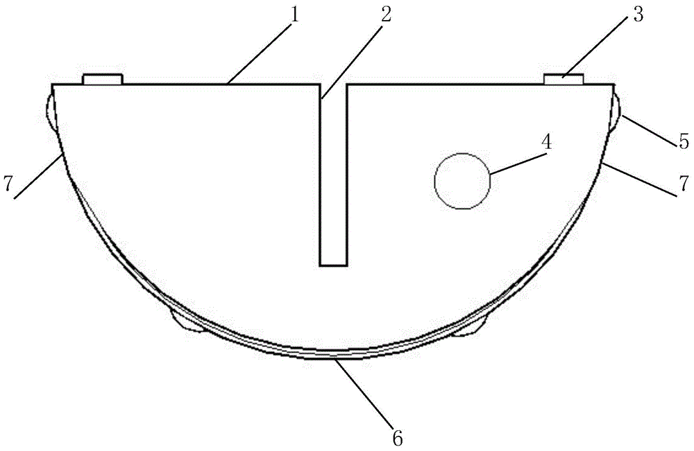
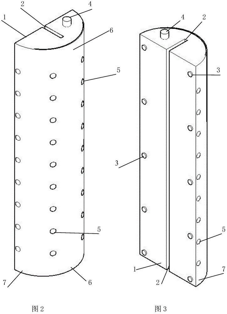
[0040] Embodiment 1, with reference to accompanying drawing: a kind of concrete engineering mold cavity mold air bag comprises hollow air bag body, and described air bag is semi-cylindrical, and the middle part of its semi-cylindrical air bag plane 1 is provided with air bag groove 2 along the length direction, The upper end of the air bag is provided with a valve 4, and the lower end is provided with a sealed bottom.

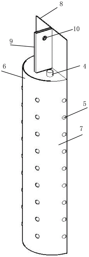
[0041] In order to facilitate airbag assembly and fixation and prevent deformation during use, the two sides of the semi-cylindrical airbag plane 1 are provided with fixed points 3 at a certain distance along the length direction, and the grooves of the airbag groove 2 and the fixed point 3 are connected to the skeleton 8. The slots 9 and the fixing holes 11 are arranged correspondingly, and are well matched to assemble the cavity mold.

[0042] In order to facilitate demoulding and achieve a certain strength, the airbag should have a certain degree of elastici...


PUM


Abstract

The invention relates to a concrete engineering cavity die gasbag which comprises a hollow gasbag body. The gasbag is in a half-cylinder shape, a gasbag groove is formed in the middle of the gasbag, and fixing points are arranged on the two sides of the gasbag groove. An inflating valve is arranged at the upper end of the gasbag, and a sealing bottom is arranged at the bottom of the gasbag. Reinforced fiber filaments are mixed into the bag wall of the gasbag. Raised points or vertical and horizontal stripes are arranged on the circular-arc outer surface of the gasbag. The gasbag and a framework are matched to form a cavity die which is arranged on the fracture surface of first-stage concrete, air pressure is set in the gasbag, and second-stage concrete is poured in a layered mode; after the concrete is initially set, the air pressure in the gasbag is released, and the cavity die is hoisted out, so that a semicircular cavity is formed in the fracture surface of the second-stage concrete, and a water stopping effect is achieved when melting bitumen is injected into the cavity; and the cavity die can be repeatedly used.

Description

technical field [0001] The invention relates to an underground / underwater building waterproof device, in particular to a concrete engineering cavity mold air bag and a manufacturing method thereof. Background technique [0002] In existing concrete structures, such as retaining dams, reservoirs, subways, culverts, sluices, tunnels and other underground and underwater projects, due to the inability to pour continuously or the deformation of the foundation settlement (earthquake), or due to temperature changes Due to thermal expansion and contraction of concrete components caused by thermal expansion and contraction, deformation joints and construction joints are often deliberately left during pouring. These gaps must take anti-leakage measures to prevent external water or groundwater from leaking into the structural space. The current common practice is A concrete groove is set between the first-stage concrete and the second-stage concrete, and soft asphalt and copper sheets ...

Claims


Application Information

Patent Timeline
Patent Type & Authority Applications(China)
IPC IPC(8): E02D29/16E02D31/02E02B3/16
CPCE02B3/16E02D29/16E02D31/02E02D2250/0007E02D2250/0023E02D2300/0001E21D11/385
Inventor 张朝利
Owner 湖南恒运建筑科技发展有限公司
Why Eureka
Try Eureka