Nozzles with automatic control of flow distribution

A technology of flow distribution and nozzles, which is applied in liquid/gas jet drilling, wellbore/well parts, earthwork drilling and production, etc. It can solve the problems of increasing drilling distance, drilling resistance, and inability of forward jet to effectively form holes, etc. problem, achieve the effect of reducing processing difficulty and reducing processing cost

Active Publication Date: 2017-04-05
BC P INC CHINA NAT PETROLEUM CORP +2
View PDF5 Cites 0 Cited by
  • Summary
  • Abstract
  • Description
  • Claims
  • Application Information

AI Technical Summary

Problems solved by technology

Although it can delay the buckling of instability, increase the drilling distance, and avoid the defects caused by the propulsion method of the rear end of the nozzle; however, since the self-drawing nozzle combination needs to distribute the flow forward and backward, the traction force is proportional to the difference between the rear and forward flow. Proportional, the increase in traction results in a decrease in the drilling capability of the forward nozzle
[0006] Due to the heterogeneity of the formation, when encountering a local rock formation with poor drillability, the forward jet cannot effectively form a hole, resulting in resistance to drilling
Based on the flow-pressure drop characteristics of the fluid delivery pipeline, the flow rate of the system is limited. If the forward jet flow rock-breaking drilling capability of the self-drawing nozzle combination is insufficient, long-distance drilling cannot be achieved, which greatly weakens the adaptability to dense formations.

Method used


Image

  • Nozzles with automatic control of flow distribution
  • Nozzles with automatic control of flow distribution
  • Nozzles with automatic control of flow distribution

Examples


Embodiment Construction

[0045] The above and other technical features and advantages of the present invention will be clearly and completely described below in conjunction with the accompanying drawings. Apparently, the described embodiments are only some of the embodiments of the present invention, not all of them.

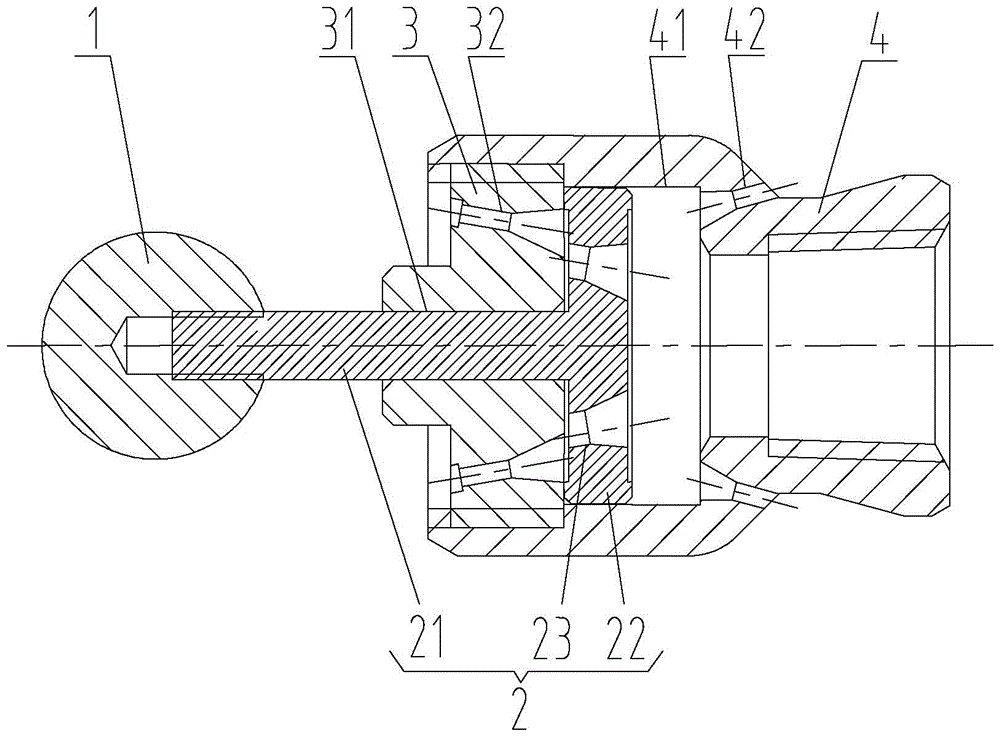
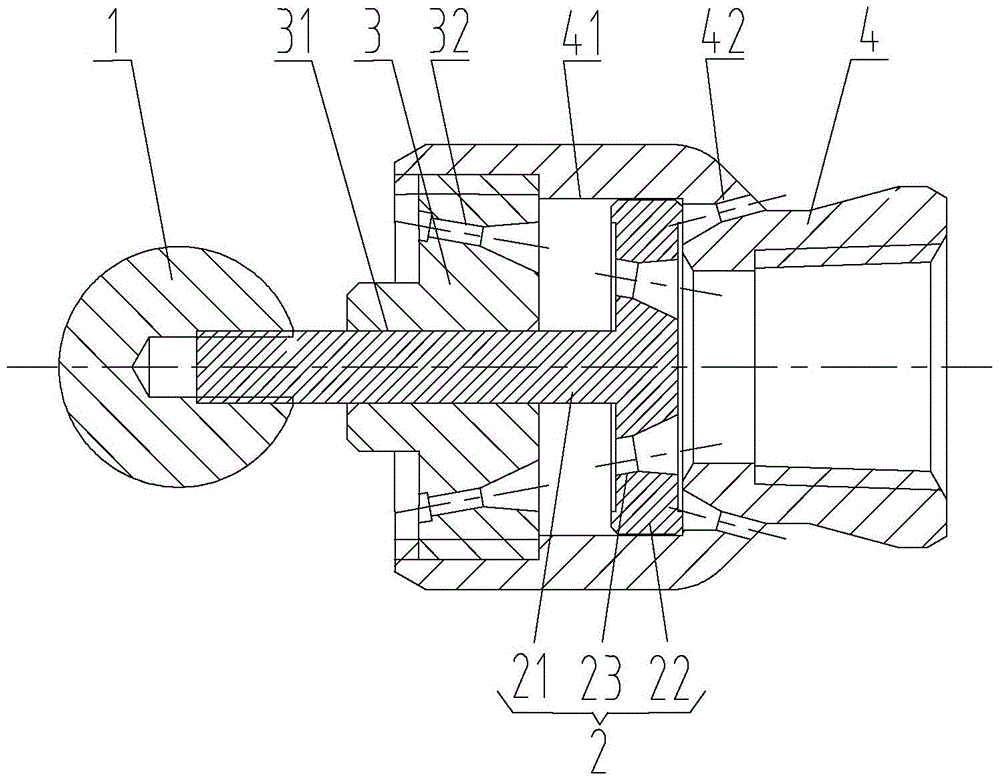
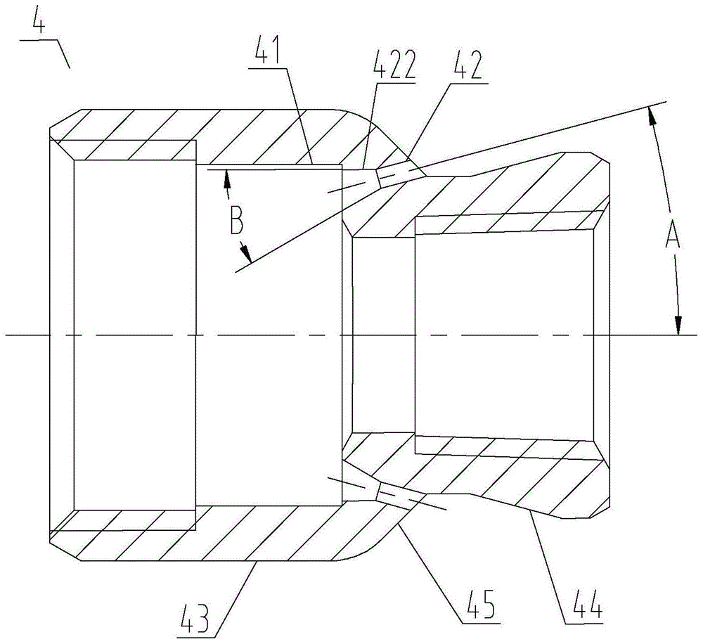
[0046] see figure 1 with figure 2 As shown, a nozzle for automatically controlling flow distribution of the present invention includes a probe 1, a reversing control rod 2, a forward nozzle 3 with a through hole and a backward nozzle 4 with a through hole. see image 3 As shown, the backward nozzle 4 includes an accommodating portion 43 and a connecting portion 44 sequentially connected along the axial direction of the through hole, and the front portion of the accommodating portion 43 is connected to the forward nozzle 3 .

[0047] recombine figure 1 with figure 2 As shown, the reversing control rod 2 includes a sliding part 22 that slides in the inner cavity of the receiving par...


PUM


Abstract

The invention provides a spray nozzle capable of automatically controlling flow distribution. The spray nozzle comprises a probe, a forward nozzle body, a backward nozzle body and a steering control rod. The backward nozzle body comprises a containing part and a connecting part which are axially and sequentially connected with each other along a through hole of the backward nozzle body. The front portion of the containing part is connected with the forward nozzle body. The steering control rod comprises a slide part sliding in an inner cavity of the containing part, and a rod part in sliding fit with a through hole of the forward nozzle body. The rod part extends out of the forward nozzle body, and the extension end of the rod part is connected with the probe. A forward spray hole and a backward spray hole which are communicated with the inner cavity of the containing part are formed in the forward nozzle body and the backward nozzle body respectively. A through flow passing hole is formed in the slide part. When the slide part slides to be tightly attached to the forward nozzle body, at least part of the section of the flow passing hole is communicated with the forward spray hole; when the slide part slides to be tightly attached to the connecting part, the slide part shields the backward spray hole; thus, distribution of forward flow and backward flow is achieved, sufficient traction is ensured during normal drilling, and meanwhile the sufficient rock break-off capacity is achieved when the spray nozzle encounters an obstacle.

Description

technical field [0001] The invention relates to the technical field of water jet drilling, and is suitable for engineering operations such as radial horizontal wells and hydraulic deep penetration in industries such as petroleum, coal, and natural gas, and particularly relates to a nozzle. Background technique [0002] The technology of water jet drilling radial horizontal well is to use screw motor and universal joint flexible shaft combination drilling tool to drill through the casing under the guidance of downhole guide, and use the high pressure water jet formed by the nozzle to break the rock and drill along the oil and gas layers. The wellbore is radially drilled with clean drainage channels up to tens of meters deep, adding and expanding the oil drainage area, improving the flow resistance characteristics of oil and gas flowing into the wellbore, and achieving increased production, increased injection and enhanced recovery. [0003] At present, the nozzles of common r...

Claims


Application Information

Patent Timeline
Patent Type & Authority Patents(China)
IPC IPC(8): E21B7/18
CPCE21B7/18E21B41/0078
Inventor 张友军张炎于东兵胡强法陈智吕维平
Owner BC P INC CHINA NAT PETROLEUM CORP
Why Eureka
Try Eureka