Volute structure, centrifugal compressor and refrigeration equipment

A centrifugal compressor and volute technology, applied in mechanical equipment, non-variable-capacity pumps, non-displacement pumps, etc., can solve the problem of reducing the performance of centrifugal compressor units, the inability of gas to be sufficiently diffused, and the operation of the unit. Stability reduction and other problems, to achieve the effect of improving the diffusion effect, improving the operating stability and compressor performance, and increasing the critical speed

Active Publication Date: 2015-03-25
GREE ELECTRIC APPLIANCES INC
View PDF10 Cites 15 Cited by
  • Summary
  • Abstract
  • Description
  • Claims
  • Application Information

AI Technical Summary

Problems solved by technology

[0004] The inventors have found that there are at least the following deficiencies in the prior art: reducing the length of the primary diffuser section will make the gas entering the centrifugal compressor unable to undergo sufficient diffusion, which will reduce the unit performance of the centrifugal compressor
However, increasing the length of the main shaft 20 will lead to a decrease in the critical speed of the compressor, a decrease in the operating stability of the unit, and a decrease in performance

Method used


Image

  • Volute structure, centrifugal compressor and refrigeration equipment
  • Volute structure, centrifugal compressor and refrigeration equipment

Examples


Embodiment Construction

[0030] Combine below figure 2 A more detailed elaboration of the technical solution provided by the present invention, a technical solution obtained by replacing any technical means provided by the present invention or combining any two or more technical means or technical features provided by the present invention with each other All should be within the protection scope of the present invention.

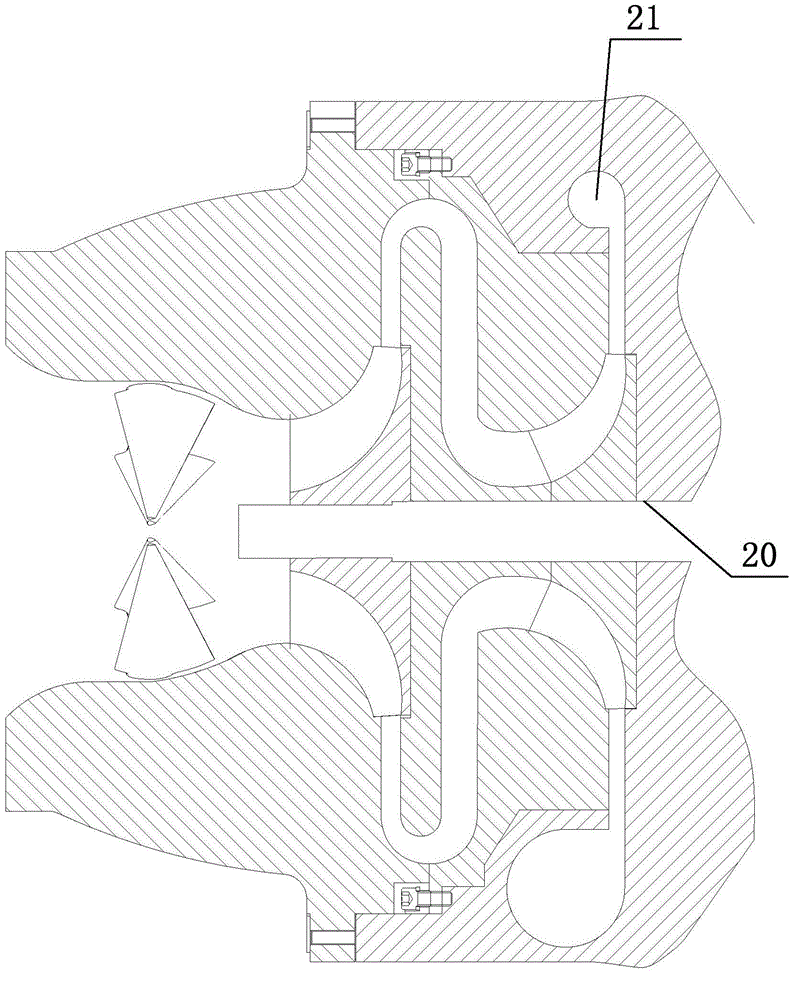
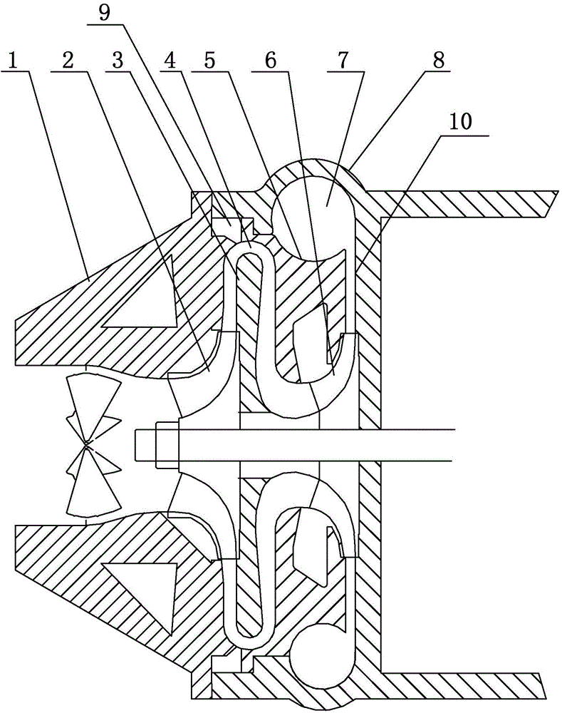
[0031] In this paper, the front and rear refer to the direction of the airflow entering the volute structure, and the one located upstream of the airflow is the front, that is, figure 2 Left side shown; downstream of airflow is rear, i.e. figure 2 shown on the right.

[0032] Embodiments of the present invention provide a volute structure, which is preferably used in centrifugal compressors and similar products, and can be set as a forward-inclined volute structure (i.e. figure 2 In the arrangement shown, the inner arc-shaped cavity of the volute casing 7 is facing the upstr...


PUM


Abstract

The invention discloses a volute structure, a centrifugal compressor and refrigeration equipment, and relates to the field of refrigeration equipment. An existing centrifugal compressor structure is optimized. The volute structure comprises a box body, a volute body and a return device. The volute body comprises an inner volute and an outer volute independent from the inner volute. A fluid channel is formed between the inner volute and the outer volute. The inner volute and the return device are arranged together. According to the technical scheme, the length of the section of a primary pressure expander can be increased so that the pressure expansion effect of gas entering the primary pressure expander can be improved, and then the unit performance of the centrifugal compressor is improved.

Description

technical field [0001] The invention relates to the field of refrigeration equipment, in particular to a volute structure, a centrifugal compressor and refrigeration equipment. Background technique [0002] In the structure of two-stage and multi-stage centrifugal compressors, in order to reduce the length of the cantilever end of the main shaft, increase the critical speed, and enhance stability, it is often necessary to make the pneumatic part of the multi-stage compression very compact. The high number of components involved makes the arrangement of the individual components of the pneumatic part of the centrifugal compressor difficult. Especially in the forward-inclined multi-stage compression of the volute, the distance between the volute and the bend behind the outlet of the first-stage diffuser is very close, and the structure cannot meet the requirements. [0003] figure 1 It is a schematic layout diagram of the pneumatic part of a two-stage centrifugal compressor ...

Claims


Application Information

Patent Timeline
Patent Type & Authority Applications(China)
IPC IPC(8): F04D29/44
CPCF04D29/441F04D17/12F04D29/4206F04D17/122F04D29/403F04D29/624F04D25/16F04D29/628
Inventor 刘建飞张治平钟瑞兴蒋楠蒋彩云谢蓉陈玉辉黄保乾
Owner GREE ELECTRIC APPLIANCES INC
Why Eureka
Try Eureka