Time-lens image-forming system

A technology of time lens and imaging system, which is applied in nonlinear optics, instruments, optics, etc., can solve the problem of insufficient clarity of optical signals, and achieve the effect of improving imaging effect and perfect matching

Active Publication Date: 2015-03-25
ZHEJIANG UNIV OF TECH
View PDF4 Cites 16 Cited by
  • Summary
  • Abstract
  • Description
  • Claims
  • Application Information

AI Technical Summary

Problems solved by technology

[0004] The second-order dispersion of the optical fiber is the basic condition for imaging, but the nonlinear effect of the optical signal will have a certain impact on the imaging results, so that there is a certain difference between the output results of the imaging system and the theoretical value, and even when the imaging conditions are satisfied. Light signal becomes less clear

Method used


Image

  • Time-lens image-forming system
  • Time-lens image-forming system
  • Time-lens image-forming system

Examples


Embodiment 1

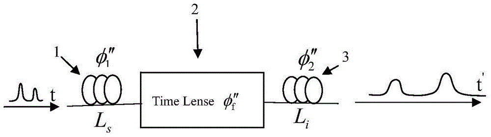
[0016] refer to Figure 1 to Figure 3 , a temporal lens imaging system, comprising an input segment optical fiber 1, a temporal lens 2, and an output segment optical fiber 3.

[0017] The dispersion parameters of the input segment optical fiber and the output segment optical fiber in the time lens imaging system all decrease exponentially, that is, β 2 (z)=β 20 exp(‐αz), where α is the loss coefficient of the fiber, β 20 is the initial value of the dispersion of the reduced dispersion fiber. Time lens 2 is realized by the four-wave mixing effect of signal light and pump light in highly nonlinear optical fiber.

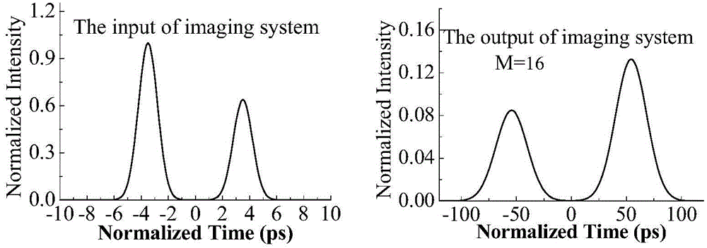
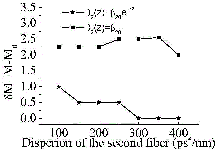
[0018] exist image 3 In, β 20 =-20ps 2 / km,α=0.21dB / km. The dispersion in the output fiber is β 20 and beta 20 In two different cases of exp(‐αz), the difference between the pulse width magnification of the time lens output signal and the theoretical value is δM, which is determined by image 3 It can be seen that after the output fiber adopts the exponentia...

Embodiment 2

[0020] A temporal lens imaging system is composed of three parts: an input section dispersive fiber 1 , a time lens 2 and an output section dispersive optical fiber 3 . Both the input section fiber 1 and the output section fiber 3 are composed of decreasing dispersion fibers, and the time lens 2 is realized by the four-wave mixing effect of signal light and pump light in a highly nonlinear silicon waveguide.


PUM


Abstract

The invention discloses an image-forming system of time-lens. The image-forming system comprises an input-section dispersive fiber, a time-lens, and an output-section dispersive fiber. The time-lens is implemented by a four-wave mixing effect of signal light and pump light in a high nonlinear fiber. Second-order dispersive parameters of the input-section dispersive fiber and the outlet-section dispersive fiber both decrease gradually according to the exponential law, and a decreasing index is equal to the loss coefficient of the fibers. According to the image-forming system of time-lens, the dispersive parameters of the inlet-section dispersive fiber and the outlet-section dispersive fiber are improved, an optimal match of a dispersion and a nonlinear effect during the transmission of signals is achieved for the signals, the magnification times of the output signals of the image-forming system of time-lens are closer to a theoretical value, and thereby the imaging effect of the time-lens is improved.

Description

(1) Technical field [0001] The invention relates to a time lens imaging system capable of amplifying or compressing optical signals. (2) Background technology [0002] A time lens is an optical device that can generate a secondary time phase shift for an optical signal. The photoelectric phase modulator can form a time lens, but the secondary phase generated is only a few π. Cross-phase modulation and sum frequency difference frequency can also form a time lens, but the power of the pump light must be very high. However, using the four-wave mixing (FWM) effect to realize the time lens does not require high power, and the phase that can be modulated can also be relatively large. In addition, in the FWM process, the wavelength of the signal light and the generated idle light are very close, so it is relatively easy to realize signal transmission and reception in the field of optical communication technology. Therefore, using FWM to implement temporal lensing has certain adva...

Claims


Application Information

Patent Timeline
Patent Type & Authority Applications(China)
IPC IPC(8): G02F1/365
CPCG02F1/365
Inventor 郭淑琴王建芬任宏亮常丽平
Owner ZHEJIANG UNIV OF TECH
Why Eureka
Try Eureka