
Dynamic balance suppression method for spatial vibration of high-speed rotor bearing system

A system space, high-speed rotor technology, applied in mechanical oscillation control, non-electric variable control, control/regulation systems, etc., can solve the problems of space vibration suppression without considering rotor displacement and bearing vibration at the same time

Inactive Publication Date: 2015-03-25
XIDIAN UNIV
View PDF6 Cites 2 Cited by
  • Summary
  • Abstract
  • Description
  • Claims
  • Application Information

AI Technical Summary

Problems solved by technology

[0005] The absolute displacement of the rotor and the relative vibration of the bearing base respectively represent the rotation accuracy and the unbalanced vibration energy. The existing research on the space vibration suppression of the rotor bearing system does not consider both the rotor displacement and the bearing vibration. They are both independently analyzed or optimized.
It is precisely because the existing dynamic balancing methods rarely consider the two types of vibrations comprehensively, and sometimes the phenomenon of taking care of one and losing the other occurs in the balancing operation.

Method used


Image

  • Dynamic balance suppression method for spatial vibration of high-speed rotor bearing system
  • Dynamic balance suppression method for spatial vibration of high-speed rotor bearing system
  • Dynamic balance suppression method for spatial vibration of high-speed rotor bearing system

Examples


Embodiment Construction

[0041] This embodiment provides the specific implementation process of the present invention in engineering practice.

[0042] 1. Acquisition of rotor displacement and bearing vibration data

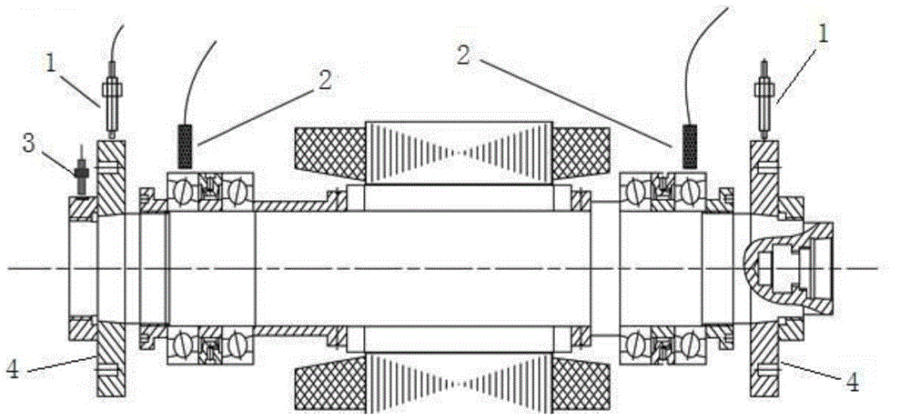
[0043] like figure 1 Shown is a schematic diagram of the model of the high-speed rotor bearing system of the present invention (only the vertical direction sensor is drawn in the figure), the structure of the high-speed rotor bearing system is the prior art, and its structure will not be described in detail here; Figure 4 It is a flow chart of the steps of the method of the present invention. The present invention collects the horizontal and vertical direction displacement signals δ of the surface of the counterweight plate through the displacement sensor 1 LH ,δ LV ,δ RH ,δ RV , through the vibration sensor 2 to collect the vibration signal υ of the bearing outer ring LH ,υ LV ,υ RH ,υ RV , collecting the phase signal through the phase detection sensor 3;

[0044] where: δ L...


PUM


Abstract

The invention discloses a dynamic balance suppression method for spatial vibration of a high-speed rotor bearing system. On the basis of testing spatial vibration of the high-speed rotor bearing system, the incidence relation between the displacement and vibration motion track area and the amount of unbalance is given, an optimized objective function involving rotor displacement and bearing vibration is established, synchronous suppression of rotor displacement and bearing vibration is achieved in combination with an optimization method, both promotion of rotor rotation precision and suppression of unbalance vibration energy are taken into consideration, and the proportions of displacement and vibration suppression effects in different directions and on different sections are controlled through configuration of weight coefficients. The dynamic balance suppression method overcomes the defects that according to traditional vibration suppression methods, rotor displacement or bearing vibration is seldom taken into comprehensive consideration, most of vibration tests are implemented only in a single direction or on a single section, and consequently it is unable to attend to everything at once occasionally. Compared with the traditional methods, the dynamic balance suppression method has the advantages that the vibration control effect of the rotor bearing system can be optimal, and the service life of the system can be prolonged effectively while the running accuracy of the system is guaranteed.

Description

technical field [0001] The invention relates to a fault diagnosis and vibration control method for rotating equipment, in particular to a dynamic balance suppression method for space vibration of a high-speed rotor bearing system. The method can simultaneously realize the comprehensive control of the absolute displacement of the high-speed rotor and the relative vibration of the bearing base. Background technique [0002] The spatial vibration trajectory of the high-speed rotor bearing system is relatively complex, but its vibration signals mostly present stable signal characteristics, such as pure unbalance vibration, and vibration caused by factors such as poor alignment, periodic cutting excitation, thermal deformation, and periodic environmental interference. However, when the unbalance fault is serious, the rotor collides and rubs during operation, and the original sinusoidal fluctuation will change into a non-stationary vibration waveform. In addition, the flexibility ...

Claims


Application Information

Patent Timeline
IPC IPC(8): G05D19/00
Inventor 章云陈贵敏邵敏孙虎
Owner XIDIAN UNIV
Learn More