
Ion injection machine internal beam detection system

A technology of ion implanter and detection system, which is applied in discharge tubes, electrical components, circuits, etc., to achieve the effects of simple system, easy assembly and production, and high collection accuracy

Inactive Publication Date: 2015-03-25
BEIJING ZHONGKEXIN ELECTRONICS EQUIP
View PDF0 Cites 0 Cited by
  • Summary
  • Abstract
  • Description
  • Claims
  • Application Information

AI Technical Summary

Problems solved by technology

At present, the types of ion implantation processes are continuously increasing, and with the narrowing of the characteristic line width and the increase of process complexity, the traditional medium beam implanter can no longer meet the requirements of this process. Therefore, the challenges faced by the ion implantation process are reflected The implantation energy develops towards the ultra-low end, while the implantation dose develops towards the high concentration. To solve this manufacturing process, it is necessary to develop a new ion implanter equipment—a low-energy and large-beam ion implanter to meet the requirements of shallow junction and large dose.

Method used


Image

  • Ion injection machine internal beam detection system
  • Ion injection machine internal beam detection system

Examples


Embodiment Construction

[0016] The present invention will be further introduced below in conjunction with the specific embodiments of the accompanying drawings. These descriptions are all illustrative, and the present invention is not limited thereto. The scope of the present invention is limited only by the scope of the appended claims.

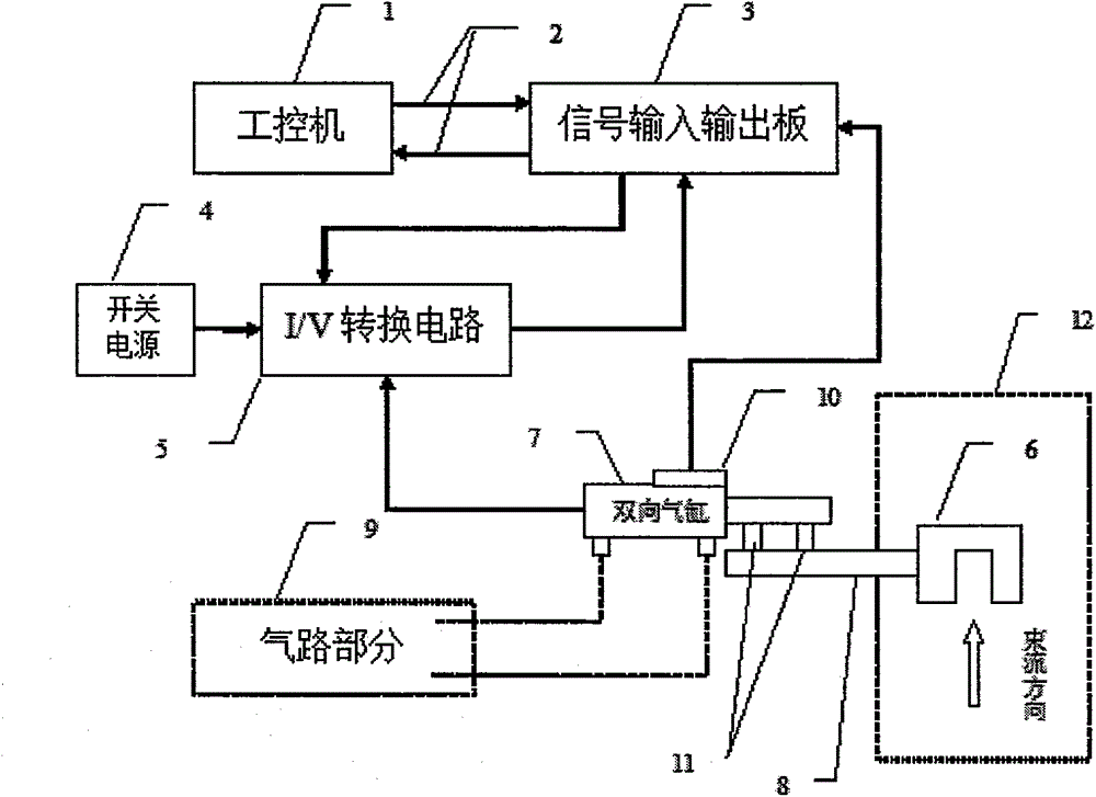
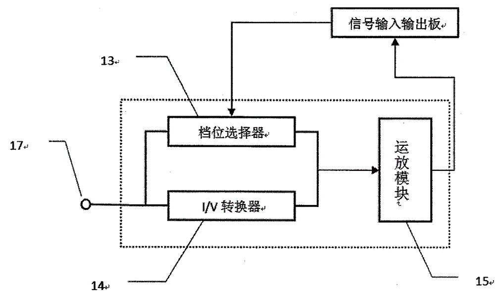
[0017] see figure 1 A beam current detection system in an ion implanter, comprising: an industrial computer (1), an optical fiber (2), a signal input and output board (3), a switching power supply (4), an I / V conversion circuit (5), and a Faraday cup ( 6), two-way cylinder (7), transmission bearing (8), air circuit part (9), in-position switch (10), fixed support frame (11), wherein the I / V conversion circuit consists of gear selector (13), It consists of an I / V converter (14) and an operational amplifier module (15).

[0018] The industrial computer (1) is connected to the signal input and output board (3) through the optical fiber (2) to send and receive data i...


PUM


Abstract

The invention relates to an ion injection machine internal beam detection system comprising an industrial control computer (1), optical fibers (2), a signal input and output board (3), a switching power supply (4), an I / V conversion circuit (5), a Faraday cup (6), a bidirectional air cylinder (7), a transmission bearing (8), an air channel part (9), an in-place switch (10) and a fixed supporting frame (11). The ion injection machine internal beam detection system is characterized in that beam values acquired by the Faraday cup (6) are transmitted to the industrial control computer (1) via the I / V conversion circuit (5) and the signal input and output board (3). Movement control is controlled by the air channel (9), and the position state of the bidirectional air cylinder (7) can be fed back to an upper computer (1). The beam detection system is reliable and stable in performance and has a shift selecting function, and acquisition precision is high so that the whole system can be flexibly controlled by the industrial control computer. The invention relates to an ion injection device, and belongs to the field of semiconductor manufacturing.

Description

technical field [0001] The invention relates to a semiconductor device manufacturing control system, that is, an ion implanter, in particular to a system for detecting the beam current extracted from the ion implanter. Background technique [0002] Integrated circuit manufacturing technology and technology are strategic projects related to the national economy and the people's livelihood. They are of great strategic significance to safeguarding national security and enhancing comprehensive national strength. They are a high-tech industry. At present, the types of ion implantation processes are continuously increasing, and with the narrowing of the characteristic line width and the increase of process complexity, the traditional medium beam implanter can no longer meet the requirements of this process, so the challenges faced by the ion implantation process are reflected The implantation energy develops towards the ultra-low end, while the implantation dose develops towards t...

Claims


Application Information

Patent Timeline
Patent Type & Authority Applications(China)
IPC IPC(8): H01J37/244
CPCH01J37/244
Inventor 田龙
Owner BEIJING ZHONGKEXIN ELECTRONICS EQUIP
Learn More