

Light conversion unit having color conversion function and application thereof
A color conversion and light conversion technology, applied in the direction of organic light-emitting device, organic light-emitting device structure, organic light-emitting device manufacturing/processing, etc. Strength, the effect of improving conversion efficiency
- Summary
- Abstract
- Description
- Claims
- Application Information
AI Technical Summary
Problems solved by technology
Method used
Image

Examples
Embodiment 1
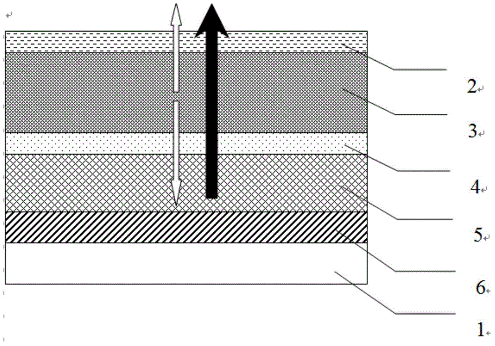
[0043] Embodiment 1 Organic electroluminescent device of top emission mode
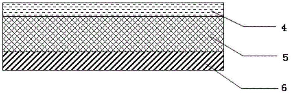
[0044] figure 2 The organic electroluminescent device shown in the top emission mode is that the reflective layer 6 is arranged on the substrate 1, and above the reflective layer 6 are a color conversion layer 5, a semi-transparent and semi-reflective conductive layer 4, and an organic functional layer 3. and the second electrode layer 2 . The light conversion unit is applied to a top-emitting white light OLED, and the top-emitting white light OLED includes a transparent electrode layer 2, a light-emitting layer 3 and figure 1 In the light conversion unit shown, the semi-transparent and semi-reflective conductive layer 4 of the light conversion unit is in contact with the light emitting layer 3 . The electroluminescence spectrum of the luminescent layer 3 contains at least blue light components, by adding yellow or red, green color conversion material CdSe / CdS quantum dots (CdS core-shell quantum dot...
Embodiment 2
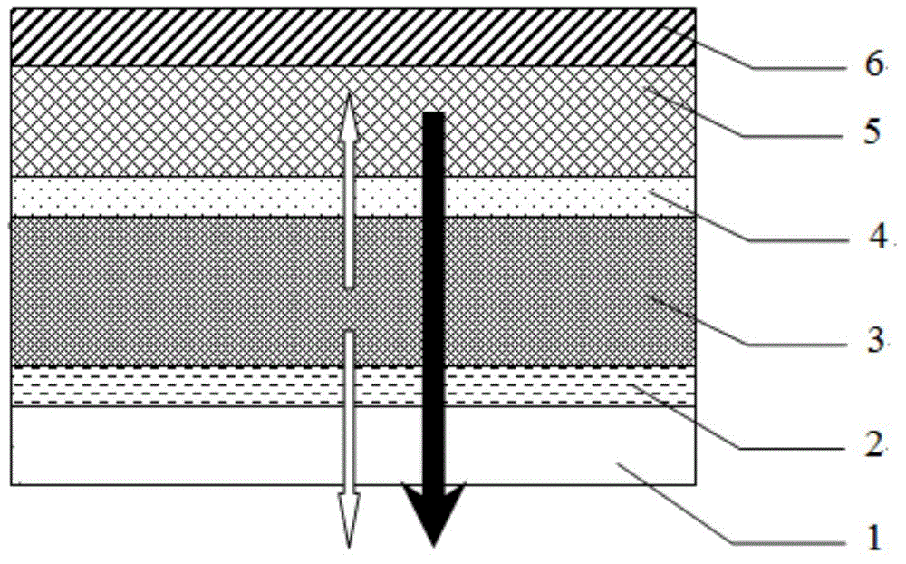
[0065] Embodiment 2 The organic electroluminescence device of bottom emission mode
[0066] image 3 The organic electroluminescent device shown as the bottom emission mode is that the organic electroluminescence device is in the bottom emission mode, the second electrode layer 2 is arranged on the substrate 1, and the above second electrode layer 2 is arranged in turn. The organic functional layer 3, the transflective conductive layer 4, the color conversion layer 5 and the reflective layer 6 are described above. The electroluminescence spectrum of the luminescent layer 3 contains at least blue light components, by adding yellow or red and green color conversion material CdSe / CdS quantum dots in the color conversion layer, and adjusting the thickness of the color conversion layer to enhance the absorption of blue light components, Finally, the conversion efficiency of the blue light component can be improved, thereby adjusting the emission spectrum of the bottom emitting dev...
PUM
| Property | Measurement | Unit |
|---|---|---|
| Thickness | aaaaa | aaaaa |
Abstract
Description
Claims
Application Information