
100G QSFP28 SR4 parallel optical transceiver module and packaging method thereof

An optical transceiver module, laser emission module technology, applied in the direction of electromagnetic transceiver, optical waveguide coupling, etc., can solve the problems of high cost, complex process, low reliability and so on

Inactive Publication Date: 2015-03-25
SHENZHEN GIGALIGHT TECH
View PDF6 Cites 8 Cited by
  • Summary
  • Abstract
  • Description
  • Claims
  • Application Information

AI Technical Summary

Problems solved by technology

Specifically, in short-distance transmission such as access network connection ports and data exchange in cloud computing data centers, 100G parallel optical modules require built-in data selectors and splitters, which makes the cost higher. Integrated data selectors and splitters Although the device has a long transmission distance, the process is complicated and the reliability is not high

Method used


Image

  • 100G QSFP28 SR4 parallel optical transceiver module and packaging method thereof
  • 100G QSFP28 SR4 parallel optical transceiver module and packaging method thereof
  • 100G QSFP28 SR4 parallel optical transceiver module and packaging method thereof

Examples


Embodiment Construction

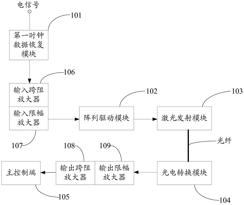
[0021] Such as figure 1 Shown is the block diagram of the 100G QSFP28 SR4 parallel optical transceiver module.

[0022] A 100G QSFP28 SR4 parallel optical transceiver module, used to transmit 100G signals in the form of optical signals; including: a first clock data recovery module 101, an array driver module 102, a laser emission module 103, a photoelectric conversion module 104 and an electrical signal processing module (not shown).

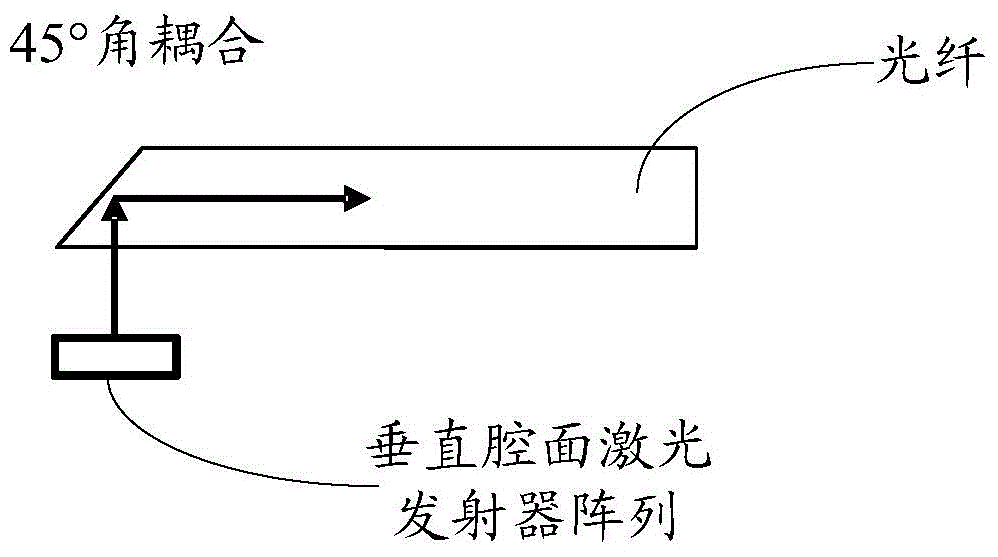
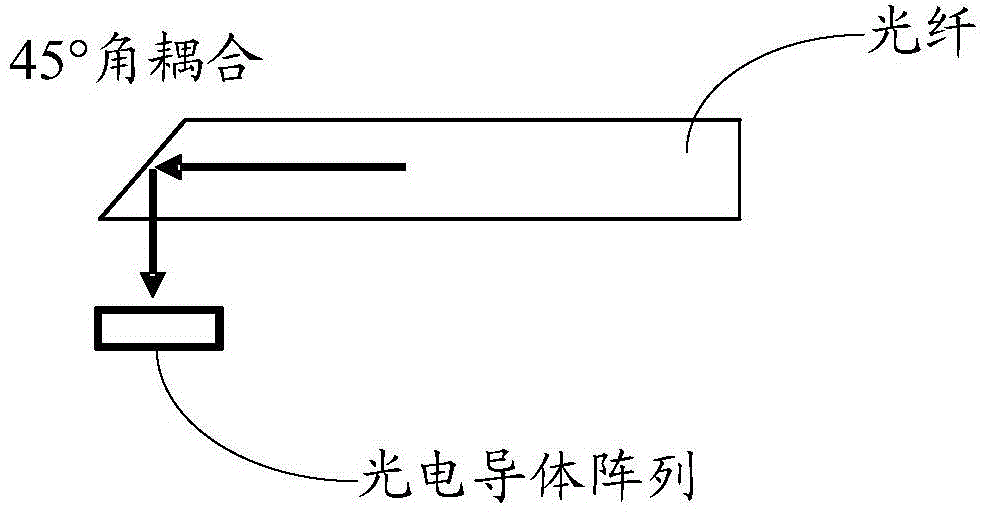
[0023] The first clock data recovery module 101 is used to perform data recovery processing on the input 100G electrical signal, and output the processed electrical signal to the array driving module 102, and the array driving module 102 is used to convert the received electrical signal The signal is modulated and demodulated, and the processed electrical signal is output to the laser emitting module 103; the laser emitting module 103 is used to convert the electrical signal into an optical signal and couple it into an optical fiber; the optic...


PUM


Abstract

A 100G QSFP28 SR4 parallel optical transceiver module carries out data recovery processing on 100G electrical signals through a first clock data recovery module so that after continuing to modulate and demodulate the electrical signals after data recovery processing is carried out, an array driving module can drive a laser transmitting module to convert the electrical signals into optical signals, then the optical signals are coupled to an optical fiber and transmitted to a photovoltaic conversion module, the photovoltaic conversion module converts the received optical signals into electrical signals, four paths of 25G electrical signals output by a master control end are converted into four paths of 25G parallel optical signals through the photovoltaic conversion module, consequently, the 100G electrical signals are propagated in the form of the optical signals, an optical multiplexer is not needed, thus the size of the 100G QSFP28 SR4 parallel optical transceiver module is reduced, and the manufacturing technology is simplified. In addition, the invention provides a packaging method of the 100G QSFP28 SR4 parallel optical transceiver module.

Description

technical field [0001] The invention relates to a parallel optical module transceiver system, in particular to a 100G QSFP28 SR4 parallel optical transceiver module with a simple structure and a packaging method thereof. Background technique [0002] With the growth of network bandwidth, the 10G rate can no longer meet the transmission requirements of communication data, and the 100G transmission rate has become an inevitable solution in application networks such as telecommunication networks and data centers. When the electrical interface and protocol standards are clear and unified, the development of 100G QSFP+ is feasible in application. Specifically, in short-distance transmission such as access network connection ports and data exchange in cloud computing data centers, 100G parallel optical modules require built-in data selectors and splitters, which makes the cost higher. Integrated data selectors and splitters Although the device has a long transmission distance, th...

Claims


Application Information

Patent Timeline
IPC IPC(8): H04B10/40G02B6/43
Inventor 杨松李振东
Owner SHENZHEN GIGALIGHT TECH
Learn More