Electrode catheter

An electrode catheter and catheter shaft technology, which is used in medical science, heating surgical instruments, and drug flushing surgical instruments, etc., can solve the problem of inability to surface perfusion of front-end electrodes, low effect of cooling on electrode surface, low thrombosis inhibition effect, and inability to perform cautery treatment, etc. problem, to achieve the effect of excellent cooling effect and excellent thrombosis inhibition effect

Active Publication Date: 2015-03-25
JAPAN LIFELINE CO LTD
View PDF5 Cites 1 Cited by
  • Summary
  • Abstract
  • Description
  • Claims
  • Application Information

AI Technical Summary

Problems solved by technology

[0008] (2) Even if physiological saline is sprayed from the opening formed on the surface of the front electrode, the surface of the front electrode cannot be sufficiently perfused (covered with liquid), so the surface of the front electrode cannot be sufficiently cooled. In addition, Inability to adequately prevent or inhibit superficial thrombus formation
In particular, in the catheters described in Patent Document 1 and Patent Document 2 that inject physiological

Method used


Image

  • Electrode catheter
  • Electrode catheter
  • Electrode catheter

Examples


no. 1 approach >

[0067] Hereinafter, one embodiment of the electrode catheter of the present invention will be described with reference to the drawings.

[0068] Figure 1 to Figure 8 as well as Figure 10 ~ Figure 13 The lead catheter shown is an ablation catheter of the present invention for use in the treatment of cardiac arrhythmias.

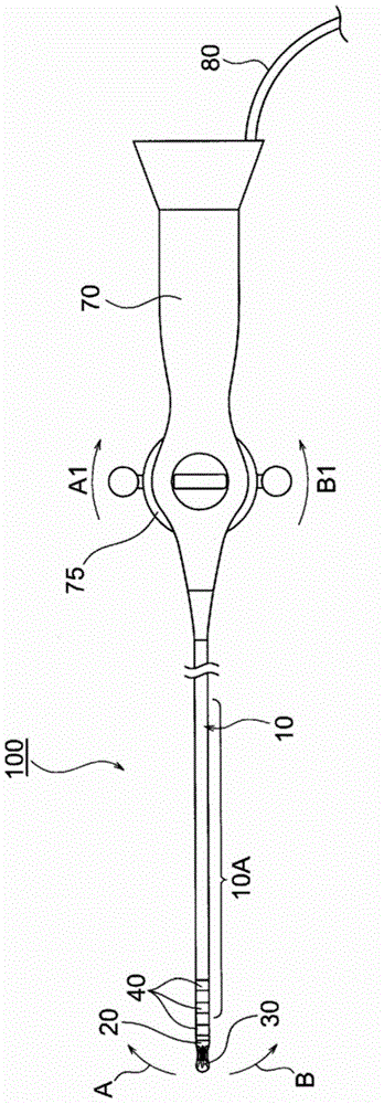
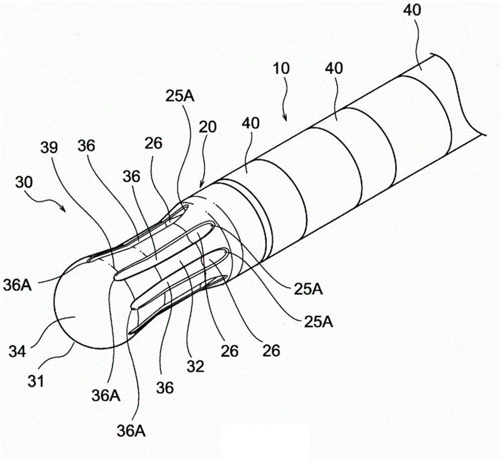
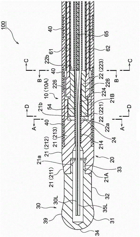
[0069] The ablation catheter 100 of the present embodiment includes: a catheter shaft 10 having a flexible distal portion 10A in which two lumens 11, 11 serving as liquid flow paths are formed eccentrically; Part 20, which is connected to the front end side of the catheter shaft 10; a front end electrode 30, which is connected to the front end side of the perfusion part 20; a ring electrode 40, which is installed on the outer peripheral surface of the catheter shaft 10; pull wires 61, 62, which Consists of a deflection mechanism for deflecting the front end flexible portion 10A of the catheter shaft 10; a leaf spring 65, which is arranged along the central...

no. 2 approach >

[0181] exist Figure 14 as well as Figure 15 The electrode catheter at the tip portion shown in the figure is the same as the first embodiment, and is the ablation catheter of the present invention used for treating cardiac arrhythmia.

[0182] The form of the distal electrode 330 constituting the ablation catheter 300 of the present embodiment is different from that of the distal electrode 30 of the first embodiment.

[0183] In addition, the structure of the ablation catheter 300 is the same as that of the ablation catheter 100 of the first embodiment except for the front end electrode. Figure 14 as well as Figure 15 In , the same reference numerals are used for the same components as those of the ablation catheter 100 .

[0184] Such as Figure 14 as well as Figure 15 As shown, the ablation catheter 300 is integrally formed with a hemispherical spherical front end portion 331 , a conical (truncated conical) base end portion 332 whose diameter is enlarged along the ...


PUM

PropertyMeasurementUnit
Outer diameteraaaaaaaaaa

Abstract

An electrode catheter is provided with: a shaft (10) having a lumen (11) serving as a fluid passage; an irrigation member (20); and a distal end electrode (30). Irrigation openings (25A) for supplying liquid, which is supplied from the shaft (10), to the surface of the distal end electrode (30) are provided in the irrigation member (20) at equal angular intervals. The distal end of the irrigation member (20) has formed therein liquid guide grooves (26) respectively extending from the irrigation openings (25A) toward the distal end. The distal end electrode (30) has a spherical distal end section (31) including a maximum-diameter section (39) and also has a proximal end section (32). Liquid guide grooves (36) are formed in the surface of the distal end electrode (30), and the liquid guide grooves (36) respectively continue to the guide grooves (26) in the irrigation member (20) and extend toward the distal end until the liquid guide grooves (36) reach at least the maximum-diameter section (39). As a result, the electrode catheter is configured in such a manner that cauterization does not cause an abnormal temperature rise in a part of the distal end electrode, that the surface of the distal end electrode exhibits an excellent cooling effect and an excellent effect of preventing the formation of a thrombus, and that the electrode catheter can perform efficient cauterization treatment.

Description

technical field [0001] The present invention relates to an electrode catheter, and more specifically, to an electrode catheter having an electrode attached to a distal end of the catheter and a mechanism for perfusing the electrode with a liquid such as physiological saline. Background technique [0002] In the ablation catheter of the electrode catheter, a perfusion mechanism is used to cool the tip electrode, which becomes high temperature during cautery, and to stir and dilute the blood around the tip electrode to prevent thrombus from forming on the surface of the tip electrode. the catheter. [0003] As a conventional catheter equipped with a perfusion mechanism, a catheter of a type in which physiological saline supplied to the inside of the tip electrode through the catheter shaft is sprayed from a plurality of openings formed on the surface of the tip electrode is introduced (for example, refer to Patent Document 1 and Patent Document 1). 2). [0004] Patent Docume...

Claims


Application Information

Patent Timeline
IPC IPC(8): A61B18/12A61B18/04
CPCA61B18/1492A61B2018/00029A61B2018/00065A61B2018/00577A61B2018/00791A61B2218/002
Inventor 森谦二
Owner JAPAN LIFELINE CO LTD
Why Eureka
Try Eureka