Contour processing clamp for bending part

A technology for shape processing and parts, applied in the field of fixtures for shape processing of curved parts, can solve the problems of radial deformation of curved parts, difficult to guarantee processing quality, increase processing difficulty, etc., achieve small deformation, ensure processing accuracy, The effect of quick processing

Active Publication Date: 2015-04-01
FUJIAN ORDNANCE EQUIP
View PDF10 Cites 3 Cited by
  • Summary
  • Abstract
  • Description
  • Claims
  • Application Information

AI Technical Summary

Problems solved by technology

Such parts are usually obtained in the form of stamping, extrusion, and spinning, especially in the form of spinning, and the parts obtained by spinning must be machined to remove flash and end faces. And the processing of the surface, groove and hole of the curved body, if the traditional three-jaw chuck is used for clamping, it is difficult to find a suitable clamping position, and it is easy to cause radial deformation of the curved body parts, which increases the difficulty of processing and cannot Guarantee the machining accuracy of parts
like figure 1 Shown is part 7, a structural schematic diagram of an armor-piercing ammunition cover, which is composed of multiple conical surfaces with different tapers and transitional arc surfaces. To remove flash, process upper and lower end surfaces and overall length, traditional mechanical equipment is used. Clamp, processing quality is difficult to guarantee

Method used


Image

  • Contour processing clamp for bending part
  • Contour processing clamp for bending part
  • Contour processing clamp for bending part

Examples


Embodiment Construction

[0024] The present invention will be described in detail below in conjunction with the drawings, and the following embodiments can enable those skilled in the art to better understand the present invention, but do not limit the present invention in any form.

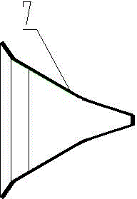
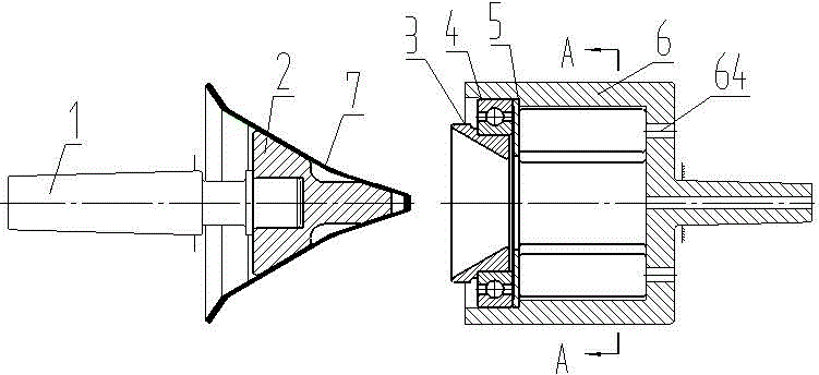
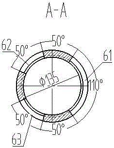
[0025] Such as figure 1 , 2 As shown, a fixture for contour processing of curved parts includes a positioning device and a clamping device. The positioning device includes a mandrel 1 and a top post 2. The top post 2 is fixed on the top of the mandrel 1. The other part of the top post 2 is The mandrel at one end matches the spindle of the lathe. The clamping device includes top bowl 3, bearing 4, gasket 5, and tip body 6. The top bowl 3 is connected to the tip body 6 through the bearing 4, and the gasket 5 is located between the bearing 4 and the tip body. In the middle of the connection surface of 6, the bearing 4 and the top bowl 3 can be easily disassembled through the four process holes 64 on the top body, the shaft...


PUM


Abstract

The invention provides a contour processing clamp for a bending part. The contour processing clamp is characterized by comprising a positioning device and a clamping device; the positioning device comprises a mandrel, and a top column which is fixed to the top end of the mandrel; the mandrel at the other end of the top column is in match with a main shaft of a lathe; the clamping device comprises a top bowl, a bearing, a spacer and a tip body; the top bowl is connected with the tip body through the bearing; the spacer is positioned in the middle of the connecting surface between the bearing and the tip body; the bearing and the top bowl can be conveniently dismounted through four process holes in the tip body; a shaft at the tail end of the tip body is in match with a tail seat of a machine tool; an inner hole in the top bowl is matched with the outer surface of a part to be processed in shape; the outer surface of the top column is matched with the inner surface of the part to be processed in shape. With the adoption of the contour processing clamp, the bending part can be conveniently mounted, and the part is avoided large deformation, so that the processing precision of the part can be ensured; the top column, the top bowl or the tip body can be replaced for contour processing of different bending parts, and therefore, the processing purpose can be conveniently and fast achieved.

Description

technical field [0001] The patent of the present invention relates to a jig for mechanical processing, especially a jig for machining the shape of curved parts. Background technique [0002] As we all know, the general shape of curved parts is conical, spherical, parabolic and so on. Such parts are usually obtained in the form of stamping, extrusion, and spinning, especially in the form of spinning, and the parts obtained by spinning must be machined to remove flash and end faces. And the processing of the surface, groove and hole of the curved body, if the traditional three-jaw chuck is used for clamping, it is difficult to find a suitable clamping position, and it is easy to cause radial deformation of the curved body parts, which increases the difficulty of processing and cannot Guarantee the processing accuracy of parts. Such as figure 1 Shown is part 7, a structural schematic diagram of an armor-piercing ammunition cover, which is composed of multiple conical surface...

Claims


Application Information

Patent Timeline
Patent Type & Authority Applications(China)
IPC IPC(8): B23Q3/00
CPCB23Q3/00
Inventor 赖启武汤子鑫余泽并黄文忠陈军赖君平林宏赵新吴昌盛张林郭存堂宋有龙
Owner FUJIAN ORDNANCE EQUIP
Why Eureka
Try Eureka