
Plunger piston shoe structure used for swash plate type axial plunger pump or motor

A technology of axial plunger pump and swash plate type, which is applied in the field of plunger pump parts, can solve the problems of affecting the working efficiency and operation of the plunger pump, increasing the use cost of the plunger pump, high manufacturing cost, etc., reaching the limit of heat treatment less, lower maintenance costs, and easy procurement

Pending Publication Date: 2015-04-01
SAIKESI HYDRAULIC TECH CO LTD
View PDF6 Cites 5 Cited by
  • Summary
  • Abstract
  • Description
  • Claims
  • Application Information

AI Technical Summary

Problems solved by technology

Since the position of the sliding shoe and the plunger requires high strength and good hardness, and the contact between the end surface of the sliding shoe and the swash plate requires good wear resistance, the base body of the existing sliding shoe adopts a steel structure, and copper must be sintered on the end surface , which makes manufacturing difficult and costly
[0005] The end face of the sliding shoe is the part that is most prone to wear. Once it is worn out, it will affect the working efficiency and operation of the plunger pump. Therefore, after the end face of the sliding shoe is worn, it needs to be replaced immediately. Since the existing sliding shoe is an integral structure, when replacing The entire slide shoe needs to be replaced; in addition, in the process of transportation and handling, if the end face is accidentally scratched, the entire slide shoe will be scrapped, which greatly increases the use cost of the plunger pump

Method used


Image

  • Plunger piston shoe structure used for swash plate type axial plunger pump or motor
  • Plunger piston shoe structure used for swash plate type axial plunger pump or motor
  • Plunger piston shoe structure used for swash plate type axial plunger pump or motor

Examples


Embodiment Construction

[0026] The present invention will be further described in detail below with reference to the embodiments of the accompanying drawings.

[0027] like Figure 1 to Figure 5 Shown is a schematic diagram of the structure of the present invention,

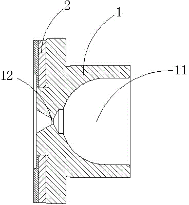
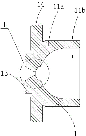
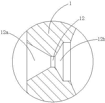
[0028] The reference signs are: sliding shoe body 1, ball-accommodating cavity 11, ball-accommodating portion 11a, extension portion 11b, oil filling hole 12, first buffer portion 12a, second buffer portion 12b, annular protrusion 13, annular edge 14 , Liner 2, copper base 21, annular groove 21a, steel base 22, through holes 23, chamfer 23a.

[0029] like Figure 1 to Figure 5 shown,

[0030] A plunger sliding shoe structure for a swash plate type axial plunger pump or motor of the present invention includes a sliding shoe body 1, and the sliding shoe body 1 is provided with a ball-accommodating cavity adapted to the head of the plunger 11. An oil filling hole 12 is provided on the main body 1 of the sliding shoe, and the oil fillin...


PUM


Abstract

The invention discloses a plunger piston shoe structure used for swash plate type axial plunger pump or motor; the plunger piston shoe structure used for swash plate type axial plunger pump or motor comprises a piston shoe body; the piston shoe body is provided with a sphere containing chamber which is matched with a plunger head; an oil injection hole is opened in the piston shoe body; the oil injection hole is communicated with the sphere containing chamber, wherein the end of the piston shoe body far away from the sphere containing chamber is fixed with a lining plate; the lining plate is made by the composition of a copper base layer and a steel base layer, the steel base layer is firmly adhered to the end face of the piston shoe body; the lining plate is detachably matched with the piston shoe body. The plunger piston shoe structure used for swash plate type axial plunger pump or motor has the advantages that a split type structure is used, the structure is simple, the machining of the piston shoe is convenient, the machining cost is reduced; only the lining plate is to be changed if the most easily damaged copper surface of the piston shoe is damaged, and the piston shoe body can still be used, thus providing convenience for maintaining the piston shoe, greatly reducing the cost of usage and maintenance, and increasing the duty cycle of the piston shoe.

Description

technical field [0001] The invention relates to a component of a plunger pump, in particular to a plunger sliding shoe structure for a swash plate type axial plunger pump or motor. Background technique [0002] The plunger pump is a positive displacement pump, a reciprocating pump. The plunger pump makes the fluid medium work through the pressure difference generated by the reciprocating motion of the plunger in the plunger cylinder, resulting in the change of the sealing volume in the plunger cylinder. The flow rate of the plunger pump can be controlled by changing the working stroke of the plunger. [0003] The swash plate axial piston pump is one of the plunger pumps. The plunger and the sliding shoe are the key components in the swash plate axial piston pump. The stroke relies on the swash plate to push the sliding shoe and the plunger to retract the plunger into the cylinder hole, while the suction stroke of the plunger relies on the concentrated spring to pull the pl...

Claims


Application Information

Patent Timeline
Patent Type & Authority Applications(China)
IPC IPC(8): F04B53/14
Inventor 王家明官柏平高魏磊胡康梁
Owner SAIKESI HYDRAULIC TECH CO LTD
Learn More