Dynamic pressure air bearing

A technology of dynamic pressure air bearings and dynamic pressure generating grooves, which is applied in the direction of bearings, shafts and bearings, mechanical equipment, etc., can solve the problems of easy influence of lubricating gas, blockage of bearing air intake, and decrease of load capacity, etc., and achieve compact structure, Stable load capacity and long life

Active Publication Date: 2017-05-03
CHINA ACAD OF AEROSPACE AERODYNAMICS
View PDF6 Cites 0 Cited by
  • Summary
  • Abstract
  • Description
  • Claims
  • Application Information

AI Technical Summary

Problems solved by technology

The above design has problems such as low rigidity, low payload, difficult packaging, and easy influence of lubricating gas, resulting in blockage of bearing air intake and reduced load capacity.

Method used


Image

  • Dynamic pressure air bearing
  • Dynamic pressure air bearing
  • Dynamic pressure air bearing

Examples


Embodiment Construction

[0025] In order to make the above objects, features and advantages of the present invention more comprehensible, specific implementations of the present invention will be described in detail below in conjunction with the accompanying drawings.

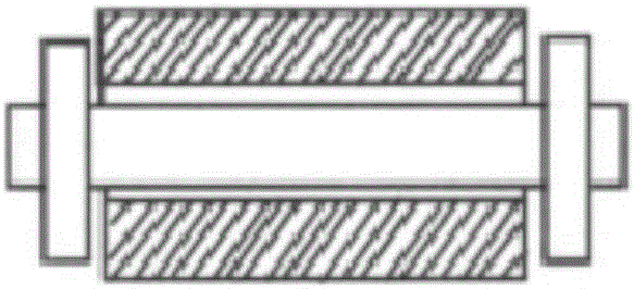
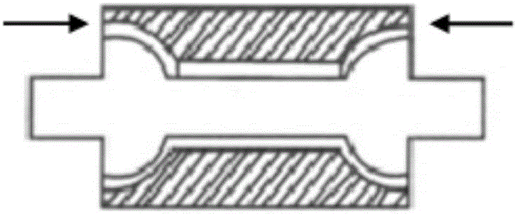
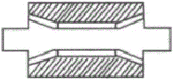
[0026] see Figure 2 to Figure 6 , the present invention provides a dynamic pressure air bearing, comprising: at least one stator 2; a rotor 1, the interior of the rotor 1 is hollow, and the rotor is rotatably sleeved on the at least one stator 2, A dynamic pressure generating groove 6 is formed on the outer peripheral surface of each stator 2 or the inner peripheral surface of a part of the rotor opposite to each stator; an air cavity 7 is defined by another part of the rotor 1 The air cavity is filled with lubricating gas, and when the rotor rotates, lubricating gas is supplied to the dynamic pressure generating groove 6 to generate dynamic pressure in the lubricating gas in the dynamic pressure generating groove.

[0027] The tradi...


PUM


Abstract

The invention discloses a dynamic-pressure gas bearing. The dynamic-pressure gas bearing comprises at least one stator, a rotor with a hollow interior and capable of freely and rotationally sleeving the at least one stator, a dynamic-pressure generation groove formed in the outer circumferential surface of each stator or the inner circumferential surface of a part opposite to each stator, of the rotor, and a gas cavity which is a space defined by the other part of the rotor and filled with a lubricating gas, wherein the lubricating gas is supplied to the dynamic-pressure generation groove during the rotation of the rotor so as to generate a dynamic pressure in the lubricating gas in the dynamic-pressure generation groove. According to the dynamic-pressure gas bearing disclosed by the invention, because the interior gas cavity is used, the gas is supplied in the interior, external packaging is not required, and the dimensions can be reduced by 50% relative to the traditional layout.

Description

technical field [0001] The invention relates to a dynamic pressure air bearing, in particular to a radial and axial composite dynamic pressure air bearing, which belongs to the technical field of gas lubricated bearings. Background technique [0002] A gas lubricated bearing is a sliding bearing that uses gas as a lubricant. Since the 1960s, with the development of emerging science and technology such as nuclear technology, aerospace technology, microelectronics technology, information technology, and bioengineering, the processing and detection accuracy has ranged from millimeters, microns to sub-microns, and has now reached the nanometer level. , and move towards the atomic lattice size (sub-nanometer) level, all these advances are dependent on the continuous improvement of ultra-precision processing and ultra-precision detection technology, the development of science and technology at this stage puts forward Higher requirements, such as high precision, large load, high s...

Claims


Application Information

Patent Timeline
Patent Type & Authority Patents(China)
IPC IPC(8): F16C32/06
Inventor 陈广强杨云军陈冰雁
Owner CHINA ACAD OF AEROSPACE AERODYNAMICS
Why Eureka
Try Eureka