
Method for rapidly starting closed-loop fiber optic gyroscope

A fiber optic gyroscope, fast start technology, applied in the field of inertial navigation, can solve the problems affecting the zero bias stability of the gyroscope, slow secondary closed-loop compensation, long compensation time, etc., to achieve the effect of improving start-up time, simple algorithm and timing

Inactive Publication Date: 2015-04-01
XIAN SINO HUAXIN MEASUREMENT & CONTROL
View PDF3 Cites 3 Cited by
  • Summary
  • Abstract
  • Description
  • Claims
  • Application Information

AI Technical Summary

Problems solved by technology

In the fiber optic gyroscope, the variation of the 2π voltage of the phase modulator (such as the Y waveguide) at high and low temperatures has a great influence on the zero bias of the fiber optic gyroscope. The closed-loop fiber optic gyroscope demodulation algorithm usually includes a closed-loop output of the gyroscope And the secondary closed loop for compensating and correcting the 2π reset voltage, in which the second closed loop is used to compensate and correct the 2π voltage, but the commonly used square wave modulation technology, at small speeds, the compensation of the secondary closed loop is relatively slow, requiring It takes a long time to complete the correction of the 2π voltage value. During this period, the zero bias of the gyro will change, causing changes in the stability of the zero bias, which is the so-called start-up time
Especially at high and low temperatures, the actual 2π voltage value of the phase modulator deviates more from the nominal 2π voltage value, and the compensation time will be longer, seriously affecting the stability of the gyroscope's zero bias, which is the same as the warm-up time table like consistent

Method used


Image

  • Method for rapidly starting closed-loop fiber optic gyroscope
  • Method for rapidly starting closed-loop fiber optic gyroscope

Examples


Embodiment Construction

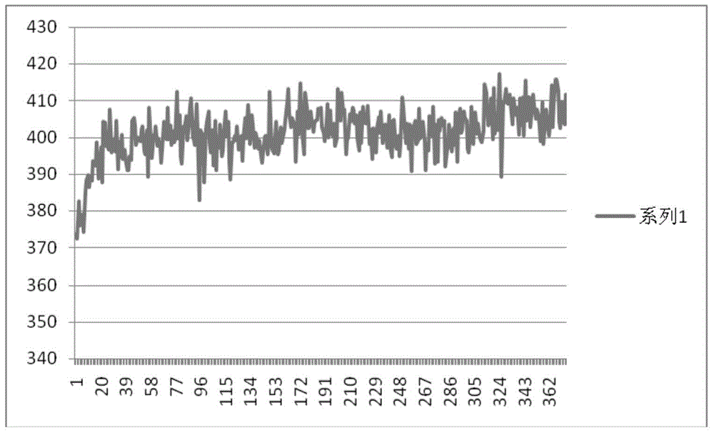
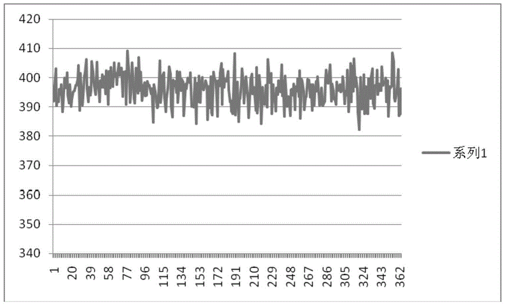
[0015] The present invention is described in further detail below in conjunction with accompanying drawing:

[0016] The method for fast start of the closed-loop fiber optic gyroscope of the present invention is realized by software algorithm. The solution of the fiber optic gyroscope is generally realized by FPGA, and the method of the present invention is also mostly completed by FPGA, and the compensation of 2π voltage is completed within 1s. Amendment, the specific implementation is as follows.

[0017] t is the working time of the fiber optic gyroscope, and the time when the fiber optic gyroscope is powered on is taken as its zero point. Set a time threshold T 启动 , and a fixed startup compensation value E, t>T 启动 Time, the secondary closed-loop method is to detect the transient value △D generated by the output power of the detector at the reset moment of square wave modulation 2π 2π , and then with this transient value △D 2π Multiplied by the secondary closed-loop com...


PUM


Abstract

The invention discloses a method for rapidly starting a closed-loop fiber optic gyroscope. The method comprises the following steps: firstly setting a time threshold value T<start> and a fixed starting compensation value E; adopting an electrification time of the fiber gyroscope as a zero point; when t is more than T<start>, a second closed-loop method is as follows: modulating an instantaneous value generated by the output power of a detector at a 2pi reset moment to be delta D2pi by adopting a detection square wave, secondarily compensating a 2pi voltage value by multiplying the instantaneous value delta D2pi by a secondary closed-loop compensation gain coefficient K, and simultaneously normally carrying out the primary closed loop of the fiber gyroscope; when t is less than or equal to T<start>, enabling the primary closed loop of the fiber gyroscope to stay at an open-loop state, and secondarily compensating the 2pi voltage value by multiplying the fixed starting compensation value E by the secondary closed-loop compensation gain coefficient K. By adopting the method, the deviation of the 2pi voltage can be rapidly compensated, and the starting time can be effectively shortened.

Description

technical field [0001] The invention belongs to the technical field of inertial navigation, and relates to a method for quickly starting a gyroscope, in particular to a method for quickly starting a closed-loop fiber optic gyroscope. Background technique [0002] Fiber optic gyroscope is a sensor device sensitive to angular velocity. It has the characteristics of high reliability, long life, short start-up time, and large dynamic range. The higher, especially the higher requirements for its startup time. For the fiber optic gyroscope itself, due to the devices used, it often takes a certain warm-up time to make the zero bias reach a stable state. However, many application fields of gyroscopes require fast response capability. Therefore, shortening the start-up time of fiber optic gyroscopes has become an important problem to be solved in engineering. [0003] There are many factors that affect the stability of the zero bias of the fiber optic gyroscope, and with the improv...

Claims


Application Information

Patent Timeline
Patent Type & Authority Applications(China)
IPC IPC(8): G01C19/72
CPCG01C19/726
Inventor 王辉杜鹃
Owner XIAN SINO HUAXIN MEASUREMENT & CONTROL
Learn More