A high-efficiency ash sampling device and method

A sampling device, ash and slag technology, applied in the direction of sampling device, etc., can solve the problems of inability to collect ash and slag samples at the first time, discontinuous sampling temperature of ash and slag samples, consuming manpower, material resources and precious time, etc. The effect of experiment time, saving experiment cost, easy to carry and install

Active Publication Date: 2016-05-11
XI AN JIAOTONG UNIV
View PDF4 Cites 0 Cited by
  • Summary
  • Abstract
  • Description
  • Claims
  • Application Information

AI Technical Summary

Problems solved by technology

[0003] However, the existing ash and slag sampling devices use water-cooled or air-cooled tube walls to allow ash or slag to deposit outside the tube wall, and can only sample ash or slag formed at a single flue gas temperature each time. Therefore, It is necessary to repeat the sampling process many times to obtain ash samples formed at multiple temperatures, which consumes a lot of manpower, material resources and precious time. In addition, due to the discontinuous sampling temperature of ash samples and the limitation of sampling site conditions, often the ash samples at critical temperatures The ash samples cannot be collected at the first time, and the experiment and collection process need to be repeated, which again causes a waste of resources and time

Method used


Image

  • A high-efficiency ash sampling device and method
  • A high-efficiency ash sampling device and method
  • A high-efficiency ash sampling device and method

Examples


Embodiment Construction

[0031] The present invention will be described in detail below in conjunction with the accompanying drawings and specific embodiments.

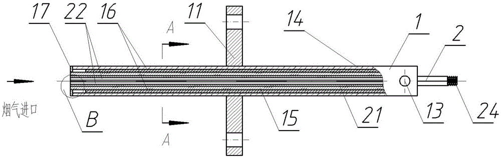
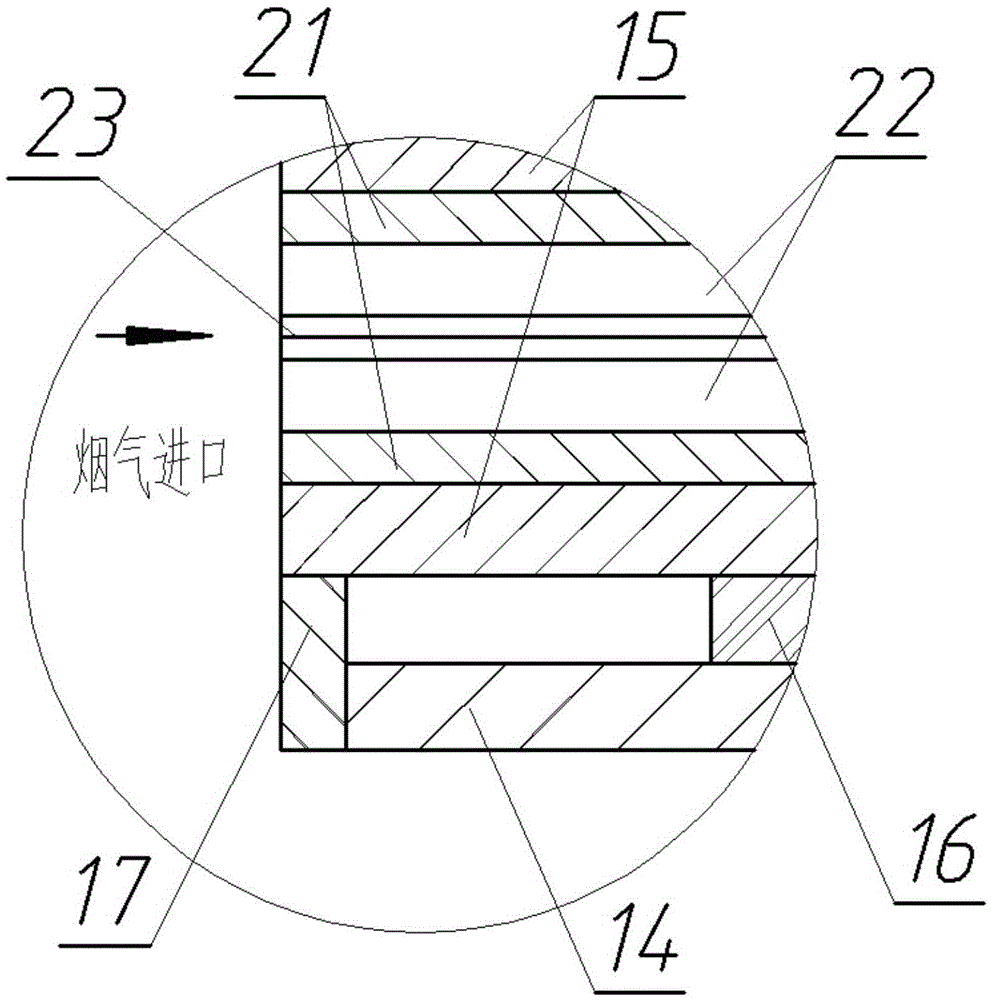
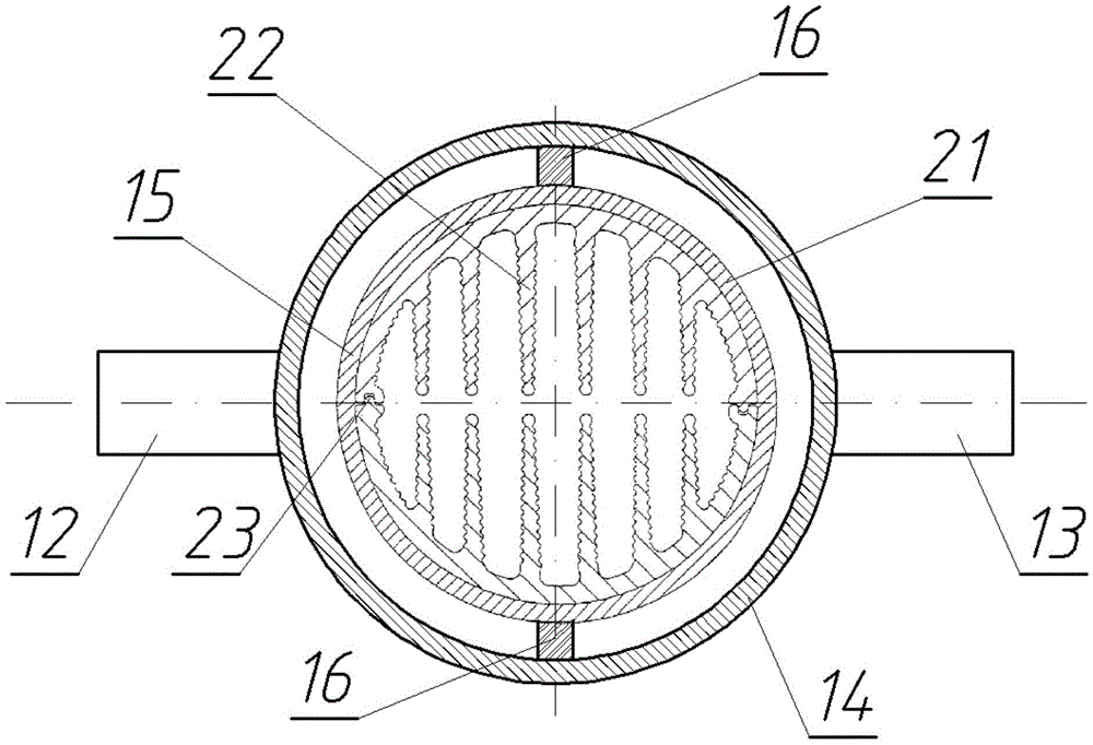
[0032] Such as figure 1 , figure 2 with image 3 As shown, a high-efficiency ash sampling device of the present invention includes a cooling jacket 1 and a sampling finned tube 2. The cooling jacket 1 includes a casing outer pipe 14 and a casing inner pipe 15, which are welded on the casing outer pipe 14 and the The two ends of the sleeve inner tube 15 are connected and the annular blocking plate 17 that seals the space between the sleeve outer tube 14 and the sleeve inner tube 15 is welded to the flange 11 on the outer wall of the sleeve outer tube 14. 14 The flue gas outlet end is provided with a working fluid inlet 12 and a working fluid outlet 13; a split rib 16 welded between the sleeve outer tube 14 and the sleeve inner tube 15, the sleeve outer tube 14 and the sleeve inner tube 15 smoke There is an unwelded split rib 16 at a preset...


PUM


Abstract

The invention relates to a high-efficiency ash sampling device and method. The high-efficiency ash sampling device comprises a cooling casing and a sampling finned pipe, wherein the cooling casing comprises a casing outer pipe, a casing inner pipe, an annular block board, a flange and a partition ribbed plate, the annular block board is in welded at the two ends of the casing outer pipe and the casing inner pipe, is used for connecting and is used for sealing a space between the two ends of the casing outer pipe and the casing inner pipe; the flange is welded on the outer wall of the casing outer pipe, and a working medium inlet and a working medium outlet are formed in the smoke outlet end of the casing outer pipe; the partition ribbed plate is welded between the casing outer pipe and the casing inner pipe and is used for partitioning the space between the casing outer pipe and the casing inner pipe into two parts communicated with the smoke inlet end; the sampling finned pipe is inserted in the casing inner pipe, is in clearance fit with the casing inner pipe and comprises a sampling finned pipe wall and sampling finned pipe inner fins, the sampling finned pipe inner fins are arranged in the sampling finned pipe, the sampling finned pipe is divided into two equal parts by taking the pipe diameter vertical to the sampling finned pipe inner fins as an axial line, and the two equal parts are mutually connected by a snap fastener. The invention further discloses the high-efficiency ash sampling method. According to the high-efficiency ash sampling device and method, experiment convenience is provided for study on a slag bonding and ash deposition mechanism of a heat exchanger, labor and materials are saved, and sampling time is shortened.

Description

technical field [0001] The invention belongs to the technical field of coal combustion and environmental pollution discharge, and in particular relates to a high-efficiency ash sampling device and method. Background technique [0002] The melted or partially melted coal ash particles entrained in the flue gas hit the furnace wall, water wall or heat exchange tubes to be cooled and solidified, and gradually thicken through continuous accumulation to form slagging. Slagging mainly occurs in the form of viscous or molten precipitates, most of which appear on the radiant heating surface. The problem of boiler slagging is an extremely complex physical and chemical problem, which is closely related to the combustion status, fuel properties and heat transfer of the boiler. Contamination is also called ash accumulation, which refers to the deposition of ash particles in the flue gas on the heating surface when it is lower than the ash melting point. Ash deposition includes two typ...

Claims


Application Information

Patent Timeline
Patent Type & Authority Patents(China)
IPC IPC(8): G01N1/20
Inventor 马海东王云刚赵钦新潘佩媛杨文君陈衡
Owner XI AN JIAOTONG UNIV
Why Eureka
Try Eureka