Digital phase discriminator used for GPS tame crystal oscillator

A digital phase detector and crystal oscillator technology, applied in the field of digital phase detectors, can solve the problems of slow adjustment speed of phase-locked loops, phase 2π ambiguity, phase detectors cannot directly measure frequency deviation, etc., and improve the ability to resist edge jitter , improve the locking speed, and facilitate the effect of timing design

Inactive Publication Date: 2015-04-01
SOUTH CENTRAL UNIVERSITY FOR NATIONALITIES
View PDF3 Cites 37 Cited by
  • Summary
  • Abstract
  • Description
  • Claims
  • Application Information

AI Technical Summary

Problems solved by technology

[0004] (1) The existing phase detector cannot directly measure the frequency deviation, but reflects the frequency deviation through the phase change difference, and the existing phase difference only measures the rising edge or the lower edge of the pulse signal, so that the frequency deviation measurement will be affected by the edge Influenced by jitter, measurement error increases
[0005] (2) In order to achieve high-precision frequency output in GPS taming active crystal oscillator applications, the signal used for phase detection requires a long period (above the second level), resulting in a very low sampling frequency for phase detection
High precision OCXO with high Q (up to 10 7 ), resulting in a very narrow voltage-controlled adjustable frequency range
The above two factors will lead to a slower adjustment speed of the PLL
Moreover, due to the randomness of the initial phase, when the existing double D fli

Method used


Image

  • Digital phase discriminator used for GPS tame crystal oscillator
  • Digital phase discriminator used for GPS tame crystal oscillator
  • Digital phase discriminator used for GPS tame crystal oscillator

Examples


Embodiment 1

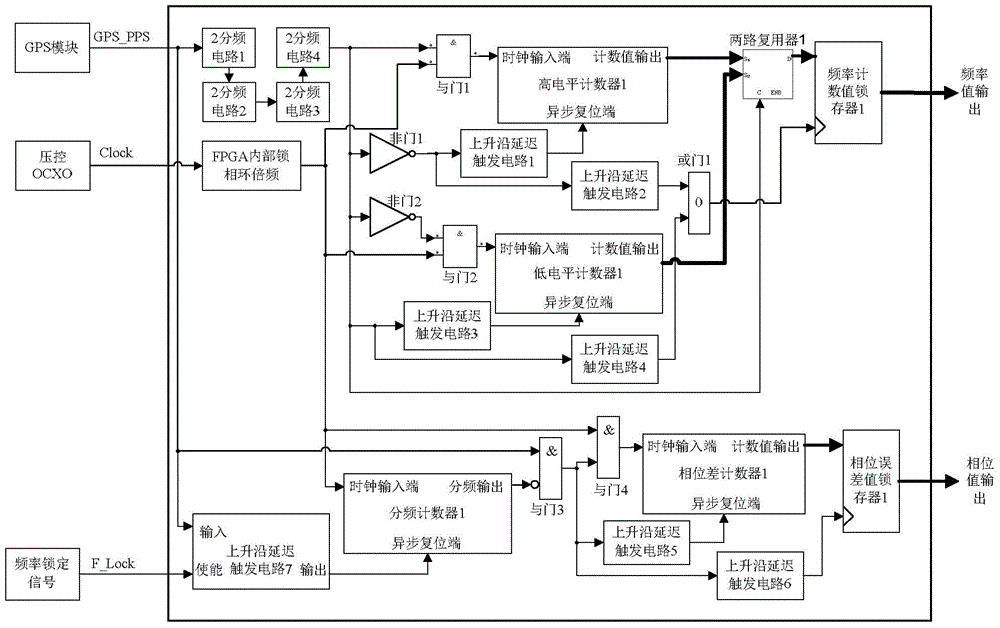
[0042] figure 1 It is the circuit structure and connection diagram of this patent. There are 3 input terminals, the first signal is the PPS signal from the GPS module, the second signal is the high-frequency clock signal from the OCXO, and the third signal is from the phase-locked loop. Outputs the coarse frequency lock status signal. There are 2 output terminals, the first one is digital frequency output, the second one is digital phase difference output.

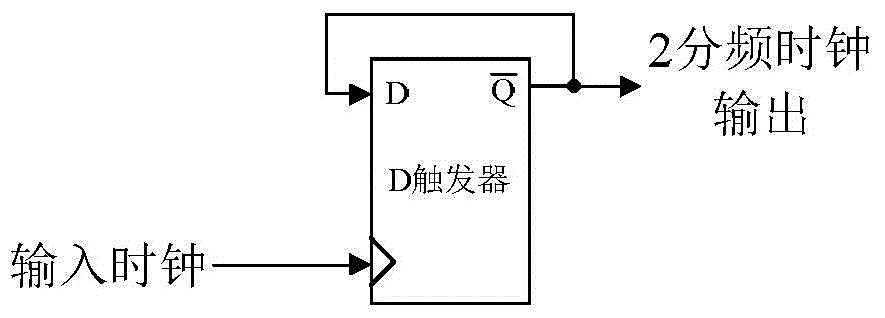
[0043] The phase detector can be divided into two parts, figure 1 The upper half is the frequency measurement circuit, and the lower half is the phase measurement circuit. The connection and work of the frequency measurement circuit are described as follows: the pin of the external input GPS_PPS signal is connected to the input terminal 1 of the frequency division circuit by 2, and the frequency division circuit plays two functions, the first function is to convert the external PPS signal into duty The ratio is 50% of...

example 1

[0052] f in example one clk =200MHz. The high-level and low-level width of the second pulse after frequency division by the 4-level 2-frequency division circuit is 8 seconds, so the capacity of the counter must be greater than 1.6×10 9 , the number of bits of high level counter 1 and low level counter 1 in example 1 is set to 32 bits. Therefore, the bit width of the frequency counting latch 1 is also 32 bits. The final frequency measurement value is output from the frequency count value latch 1, and the value in the latch is refreshed every 8 seconds, and the refresh time is the delay T after the rising edge and falling edge of the second pulse after 16 frequency division d2 long moments. When using, pay attention to reading the frequency count value latch 1 synchronously with the GPS PPS signal, and avoid the data refresh time.

[0053] The second part of the phase detector, namely figure 1 The phase error measurement circuit in the middle and lower parts realizes the p...


PUM


Abstract

The invention discloses a digital phase discriminator used for a GPS tame crystal oscillator. The digital phase discriminator used for the GPS tame crystal oscillator comprises a 2N frequency divider, a high level pulse width counter, a low level pulse width counter, a pulse per second clock, a phase difference counter clock, a frequency count value latch and a phase error value latch. The 2N frequency divider is used for performing frequency division on 1 Hz PPS signals output by a GPS module. The high level pulse width counter and the low level pulse width counter are used for counting high level pulse widths and low level pulse widths. The pulse per second clock is in input connection with frequency locking enabled signals provided by the outside, is connected with the GPS and performs frequency diversion on inner pulse per second signals output by an OCXO clock. The phase difference counter clock inputs the inner pulse per second signals and PPS signals output by the GPS module, calculates the time difference of rising edges of the inner pulse per second signals and rising edges of the PPS signals, and outputs count values of the phase difference. The frequency count value latch and the phase error value latch are used for achieving the frequency at which an OCXO tracks GPS signals and the PPS signals and meanwhile output frequency values and phase error values. According to the digital phase discriminator used for the GPS tame crystal oscillator, time sequence design is facilitated, and the problem of lead-lag fuzziness of initial phase errors is avoided; the scheme of serial counters is adopted in the frequency counter and the phase measurement counter, so the frequency of the counter clock will not be affected by counting digits.

Description

technical field [0001] The invention belongs to the field of phase detectors, in particular to a digital phase detector used for GPS taming crystal oscillators. Background technique [0002] The digital phase detector is an essential part of the digital phase-locked loop. Its basic function is to measure the time difference between the input clock signal and the edge of the reference clock signal, reflect the phase difference, and output the leading phase value and the lagging phase according to the leading and lagging conditions. value. The commonly used digital phase detector is a double D flip-flop phase detector, and the output signal has an analog output mode in which the pulse width represents the phase difference; there is also a digital output mode in which a timing counter counts the time difference of the edge and outputs a digital quantity; the time difference of the timing edge is generally used High-speed clock counts to measure the time difference, and there i...

Claims


Application Information

Patent Timeline
IPC IPC(8): H03L7/085H03L7/18
Inventor 陈锟宁百齐朱正平孙奉娄蓝加平胡连欢林邓国
Owner SOUTH CENTRAL UNIVERSITY FOR NATIONALITIES
Why Eureka
Try Eureka