A preparation method and equipment for a coating layer of an electric heating network

A technology of coating layer and electric heating network, which is applied in the direction of coating, liquid coating device on the surface, pretreatment surface, etc., can solve the problems of complex coating layer of electric heating network, cumbersome production process, poor product quality control, etc. , to achieve the effect of easy quality control, long service life and simple structure

Active Publication Date: 2017-04-12
四川中升博能生物科技股份有限公司
6 Cites 0 Cited by

AI-Extracted Technical Summary

Problems solved by technology

In the prior art, most of the equipment for preparing the coating layer of the electric heating network is relatively c...

Method used

As an optional mode, in the above-mentioned equipment for preparing the coating layer of electric heating network, the whole of the equipment is tower-shaped, and the dip-coating area, the hot-air drying area, and the thermal curing area are successively distributed in the tower from bottom to top body. The main components of the equipment are concentrated in a tower structure from bottom to top, the overall structure is more compact, space-saving, and conducive to the continuity of production and high production efficiency.
As an optional mode, in the above-mentioned equipment for preparing the coating layer of the electric heating network, the dipping zone includes the first dipping tank and the second dipping tank, and the base material is completed in the first dipping tank After dipping, it is dried and thermally cured once, and then enters the second dipping tank to repeat the dipping-drying-curing process. The way of entering the base material in the first dip-coating tank and the second dip-coating tank is opposite, for example, entering in the first dip-coating tank in a counterclockwise direction, and entering in the first dip-coating tank in a clockwise direction. When the dip coating area is mainly composed of a dip coating tank containing guide rollers, in order to keep the base material in a taut state and maintain a certain tension, the base material needs to enter the dip coating tank against the guide rolls, due to the friction with the guide rolls , the amount of coating on the side of the base material in contact with the guide roller is usually slightly less, which will cause uneven coating on both sides to a certain extent. Combined with guide rollers for dip coating, the uniformity of the layer can be improved. As an optional mode, a plurality of first dip-coating tanks and second dip-coating tanks can be set in one tower body, and the base material can enter the dip-coating tanks in the order of 1-2-1-2... during operation, and also It can enter the dip coating tank in the order of 1-1…-2-2….
As shown in Figure 1, a kind of equipment that is used to prepare the coating layer of electric heating network, the whole equipment is tower-shaped, comprises tower body and is distributed in dip-coating area, hot-air drying area, hot-air drying area, thermal The curing area, the hot air drying area and the thermal curing area are respectively connected with the high temperature furnace and the fan through the air supply pipe, and the high temperature air generated in the high temperature furnace is sent into the hot air drying area and the thermal curing area respectively through the fan, and the hot air is dried at the same time. The air in the cooling zone and the thermal curing zone is recovered or emptied after the temperature is lowered. A plurality of guide rollers are arranged in the tower body, and a traction mechanism is arranged outside the tower body. The traction mechanism is used to pull the product to drive the coating to be coated. The base material moves in the equipment, and the dip coating area is mainly composed of a dip coating tank containing guide rollers, including a first dip coating tank and a second dip coating tank, and the base material is in the first dip coating tank After the dip coating is completed in the middle, it is dried and thermally cured in sequence, and then enters the second dip coating tank to repeat the dip coating-drying-curing process. The way of entering the base material in the first dip-coating tank and the second dip-coating tank is opposite, for example, entering in the first dip-coating tank in a counterclockwise direction, and entering in the first dip-coating tank in a clockwise direction. In order to...

Abstract

The invention discloses a preparation method and equipment of a coating layer of an electric heating net. The preparation method comprises the following steps: dipping a base material to be coated in a sizing agent of a coating layer material; carrying out hot air drying; carrying out hot solidification under hot air; the preparation method is simple to operate, the product is stable in performance, the quality is easy to control and the service life is long. The equipment comprises a dip-coating groove, a hot air drying area and a hot solidification area. The equipment is simple in structure and convenient to use and is capable of carrying out large-scale continuous production. By using the equipment, not only a conductive layer, but also an insulating layer can be prepared, and the prepared coating layer is uniform in structure and stable in performance.

Application Domain

Technology Topic

Image

  • A preparation method and equipment for a coating layer of an electric heating network
  • A preparation method and equipment for a coating layer of an electric heating network
  • A preparation method and equipment for a coating layer of an electric heating network

Examples

  • Experimental program(4)

Example Embodiment

[0036] Example 1
[0037] A device for preparing a coating layer of an electric heating network, comprising a dip coating area, a hot air drying area, and a heat curing area arranged in sequence. When in use, inject the slurry of the coating layer material into the dip coating area, and then send the base material to be coated to the dip coating area to be immersed in the slurry of the coating layer material, so that the slurry of the coating layer material wets the substrate The surface of the material, and then immediately sent to the hot air drying area, under the action of hot air, the coating material slurry coated on the surface of the base material is gradually dried, and then sent to the heat curing area, under the action of hot air at a higher temperature to achieve Thermal curing of coating layers. The equipment adopts simple structure and convenient operation, and the prepared coating layer has uniform structure and stable performance.
[0038]As an option, in the above-mentioned equipment for preparing the coating layer of the electric heating grid, a guide roller and a traction mechanism are also included. The finished product is pulled by the traction mechanism, and the base material to be coated is driven to move in the equipment, which can realize large-scale continuous production, and the smooth steering of the product or base material can be realized by guiding the roller at an appropriate position to make it move more smoothly , while the product or base material can always maintain a certain tension. As an option, a drum with a driving device can be used to roll the product onto the drum by rotating the drum, achieving the functions of traction and product collection at the same time.
[0039] As an option, in the above equipment for preparing the coating layer of the electric heating grid, the dip coating area is mainly composed of a dip coating tank containing guide rollers. It is convenient to keep the network structure at a certain tension during the dip coating process, avoiding loosening and sliding of the network structure due to insufficient tension, and also avoiding cracks in the coating layer caused by large changes in tension.
[0040] As an optional manner, in the above-mentioned equipment for preparing the coating layer of the electric heating grid, the dip coating area includes a plurality of dip coating tanks and guide rollers. Facilitates multiple re-dip coatings.
[0041] As an alternative, in the above-mentioned equipment for preparing the coating layer of the electric heating grid, the equipment is in the shape of a tower as a whole, and the dipping zone, the hot air drying zone, and the thermal curing zone are sequentially distributed in the tower body from bottom to top. The main components of the equipment are concentrated in a tower structure from bottom to top, the overall structure is more compact, space-saving, and conducive to the continuity of production and high production efficiency.
[0042] As an optional mode, in the above-mentioned equipment for preparing the coating layer of the electric heating net, the hot air drying area and the thermal curing area are respectively connected with the high temperature furnace and the fan through the air supply pipe, and the high temperature generated in the high temperature furnace is discharged by the fan. The air is sent into the hot air drying area and the heat curing area respectively, and at the same time, the air after the temperature in the hot air drying area and the heat curing area is lowered is recovered or evacuated.
[0043] As an optional way, in the above-mentioned equipment for preparing the coating layer of the electric heating network, a plurality of guide rollers are arranged in the tower body, and a traction mechanism is arranged outside the tower body, and the traction mechanism is used to pull the product to drive the The coated substrate material moves in the apparatus. The use of a traction mechanism can drive the smooth movement of the base material in each area.
[0044] As an option, in the above-mentioned equipment for preparing the coating layer of the electric heating grid, a plurality of tower bodies are arranged in series. The base materials in multiple tower bodies can move smoothly under the action of a traction mechanism and maintain a certain tension. The coating process can be repeated to increase the thickness of the coating layer through the towers arranged in series, and the slurry of the conductive layer material can also be added in the dip coating area of ​​the front tower body, and the slurry of the conductive layer material can be added in the dip coating area of ​​the rear tower body Add the slurry of the insulating layer material to the coating to realize the smooth completion of the conductive layer coating and the insulating layer coating in one set of equipment.
[0045] As an alternative, in the above-mentioned equipment for preparing the coating layer of the electric heating grid, multiple dip coating tanks are arranged in one tower body, so that the dip coating-drying-curing process can be repeated many times.
[0046] As an alternative, in the above-mentioned equipment for preparing the coating layer of the electric heating network, the dipping zone includes a first dipping tank and a second dipping tank, and the base material is dipped in the first dipping tank Dry and heat-cure once, and then enter the second dip-coating tank to repeat the dip-dry-cure process. The way of entering the base material in the first dip-coating tank and the second dip-coating tank is opposite, for example, entering in the first dip-coating tank in a counterclockwise direction, and entering in the first dip-coating tank in a clockwise direction. When the dip coating area is mainly composed of a dip coating tank containing guide rollers, in order to keep the base material in a taut state and maintain a certain tension, the base material needs to enter the dip coating tank against the guide rolls, due to the friction with the guide rolls , the amount of coating on the side of the base material in contact with the guide roller is usually slightly less, which will cause uneven coating on both sides to a certain extent. Combined with guide rollers for dip coating, the uniformity of the layer can be improved. As an optional mode, a plurality of first dip-coating tanks and second dip-coating tanks can be set in one tower body, and the base material can enter the dip-coating tanks in the order of 1-2-1-2... during operation, and also It can enter the dip coating tank in the order of 1-1…-2-2….
[0047] As an option, in the above-mentioned equipment for preparing the coating layer of the electric heating grid, the dip coating tank is connected to the dip coating slurry supply device through a pipeline. The slurry is provided directly through the pipeline, which is convenient for operation. A control valve can also be provided on the pipeline.
[0048] As an option, in the above-mentioned equipment for preparing the coating layer of the electric heating net, the feed of the equipment is directly connected with the output of the net structure weaving equipment for the electric heating net. The tension existing between the braided wires during the weaving process can be preserved, and the equipment of the whole system can also be simplified.

Example Embodiment

[0049] Example 2
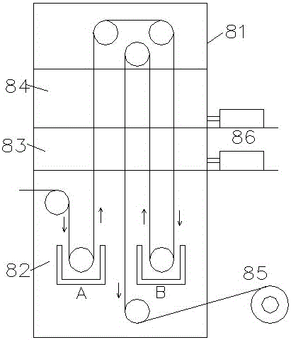
[0050] like figure 1 As shown, a kind of equipment for preparing the coating layer of the electric heating network, the whole equipment is in the shape of a tower, including the tower body and the dip coating area, the hot air drying area and the heat curing area distributed in the tower body from bottom to top in sequence, the hot air The drying area and the heat curing area are respectively connected with the high temperature furnace and the fan through the air supply pipe, and the high temperature air generated in the high temperature furnace is sent to the hot air drying area and the heat curing area respectively through the fan, and the hot air drying area and the heat curing area After the temperature is lowered, the air is recycled or emptied. There are multiple guide rollers in the tower body, and a traction mechanism is provided outside the tower body. The traction mechanism is used to pull the product to drive the base material to be coated in the equipment The dipping area is mainly composed of a dipping tank containing guide rollers, including a first dipping tank and a second dipping tank, and the substrate material is dipped in the first dipping tank in turn. Carry out drying and thermal curing and then enter the second dipping tank to repeat the dipping-drying-curing process. The way of entering the base material in the first dip-coating tank and the second dip-coating tank is opposite, for example, entering in the first dip-coating tank in a counterclockwise direction, and entering in the first dip-coating tank in a clockwise direction. In order to keep the base material in a taut state and maintain a certain tension, the base material needs to enter the dipping tank against the guide roll. Due to the friction with the guide roll, the coating amount on the side of the base material that is in contact with the guide roll is usually slightly less , it will cause uneven coating on both sides to a certain extent, and the base material can be dip-coated on the opposite side of the guide roller through the first dip-coating tank and the second dip-coating tank, which can improve the uniformity of the layer.
[0051] As an optional way, a drum with a driving device can be used to roll the product onto the drum by rotating the drum to achieve the functions of traction and product collection at the same time.
[0052] As an option, in the above-mentioned equipment for preparing the coating layer of the electric heating grid, a plurality of tower bodies are arranged in series. The base materials in multiple tower bodies can move smoothly under the action of a traction mechanism and maintain a certain tension. The coating process can be repeated to increase the thickness of the coating layer through the towers arranged in series, and the slurry of the conductive layer material can also be added in the dip coating area of ​​the front tower body, and the slurry of the conductive layer material can be added in the dip coating area of ​​the rear tower body Add the slurry of the insulating layer material to the coating to realize the smooth completion of the conductive layer coating and the insulating layer coating in one set of equipment.
[0053] As an option, in the above-mentioned equipment for preparing the coating layer of the electric heating grid, the dip coating tank is connected to the dip coating slurry supply device through a pipeline. The slurry is provided directly through the pipeline, which is convenient for operation. A control valve can also be provided on the pipeline.
[0054] As an option, in the above-mentioned equipment for preparing the coating layer of the electric heating net, the feed of the equipment is directly connected with the output of the net structure weaving equipment for the electric heating net. The tension existing between the braided wires during the weaving process can be preserved, and the equipment of the whole system can also be simplified.

Example Embodiment

[0055] Example 3
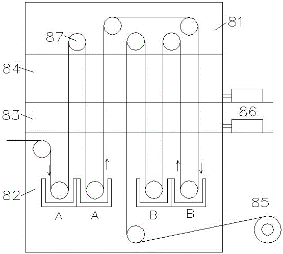
[0056] A kind of equipment for preparing the coating layer of electric heating network, the difference between the equipment and the equipment described in Example 2 is only that: the dip coating area in the tower body includes two first dip coating tanks and two a second dipping tank. When in use, the substrate first enters the first first dip-coating tank for dip-coating, then passes through the hot-air drying zone and heat-curing zone upwards for drying and thermal curing, and then enters the second first dip-coating tank downwards and then goes up sequentially. Pass through the hot air drying area and heat curing area for drying and heat curing, then go down to the first and second dip coating tanks, then go up and pass through the hot air drying area and heat curing area in turn for drying and heat curing, and then go down to the second Two dip coating tanks, and then pass through the hot air drying zone and heat curing zone upwards for drying and thermal curing (this process is to enter the dip coating tank in the order of 1-1...-2-2...), and finally in the middle traction mechanism Collect products under traction.
[0057] As an optional way, it is also possible to make the base material enter the dip coating tank in the order of 1-2-1-2... by properly setting guide rollers in the above device.

PUM

PropertyMeasurementUnit
Viscosity10.0 ~ 5000.0mPa·s
tensileMPa
Particle sizePa
strength10

Description & Claims & Application Information

We can also present the details of the Description, Claims and Application information to help users get a comprehensive understanding of the technical details of the patent, such as background art, summary of invention, brief description of drawings, description of embodiments, and other original content. On the other hand, users can also determine the specific scope of protection of the technology through the list of claims; as well as understand the changes in the life cycle of the technology with the presentation of the patent timeline. Login to view more.

Similar technology patents

Headphone apparatus

InactiveUS20060104471A1Easy to changeEasy to operateHeadphones for stereophonic communicationSupra/circum aural earpiecesAcoustic propertyEngineering
Owner:SONY CORP

Classification and recommendation of technical efficacy words

  • Product performance is stable
  • Easy to operate

Alcohol-based fuel oil

ActiveCN103184081AProduct performance is stableClean and environmentally friendly oxygen contentLiquid carbonaceous fuelsSolventGlycerol
Owner:DONGGUAN CITY QUAN RAN TRADING
Why Eureka
Try Eureka