Jig and method of using jig for machining camera lenses

A camera and fixture technology, which is applied to machine tools, metal processing equipment, lenses, etc., which are suitable for grinding the edge of workpieces, can solve the problems of large product size error, low yield rate, and low production efficiency, so as to avoid product The effect of chipping, increasing output and improving production efficiency

Inactive Publication Date: 2015-04-08
深圳市尊宝精密光学有限公司
View PDF5 Cites 8 Cited by
  • Summary
  • Abstract
  • Description
  • Claims
  • Application Information

AI Technical Summary

Problems solved by technology

[0005] The technical problem to be solved by the present invention is to provide a jig and a method for processing camera lenses using it, aiming to solve the problems of low production efficiency, large errors in product dimensions and low yield in the production of camera lenses in the prior art The problem

Method used


Image

  • Jig and method of using jig for machining camera lenses
  • Jig and method of using jig for machining camera lenses
  • Jig and method of using jig for machining camera lenses

Examples


Embodiment Construction

[0026] In order to make the technical problems, technical solutions and beneficial effects to be solved by the present invention clearer, the present invention will be further described in detail below in conjunction with the accompanying drawings and embodiments. It should be understood that the specific embodiments described here are only used to explain the present invention, not to limit the present invention.

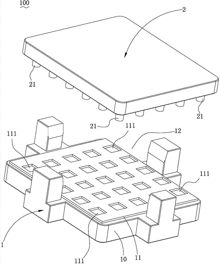
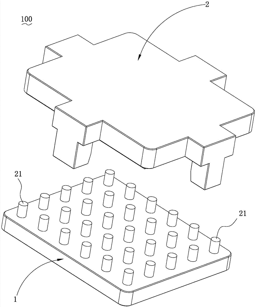
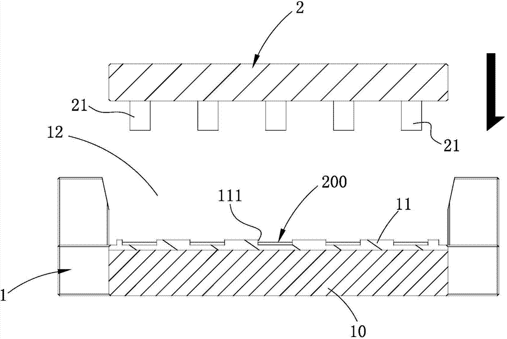
[0027] Such as figure 1 and image 3 Shown is a preferred embodiment of the present invention, a jig 100, including a first jig 1 and a second jig 2, the first jig 1 is provided with a groove for placing the lens material 200 to be processed 111 , the thimble 21 extends vertically from the position corresponding to the groove 111 on the second jig 2 , when the first and second jigs 1 and 2 are closed, the thimble 21 can be embedded in the corresponding groove 111 .

[0028] Specifically, the first jig 1 is provided with a plurality of grooves 111 , and the second...


PUM


Abstract

The invention is applicable to the technical field of lens machining and provides a jig and a method of using the jig for machining camera lenses. The jig comprises a first jig and a second jig, the first jig is provided with grooves used for placement of to-be-machined lens materials, and ejector pins vertically extend at positions, corresponding to the grooves, of the second jig and can be embedded in the corresponding grooves. The to-be-machined lens materials are placed on the jig, the jig can be fixed by a CNC (computer numerical control) machine tool by means of vacuum suction due to the fact that the size of the jig is larger than that of the lens materials, and accordingly CNC machining can be carried out. By means of the CNC machining process, adoption of a profiling machine for profiling and a beveling machine for beveling in the traditional process is replaced, and manual intervention is reduced; in addition, owing to precision of CNC equipment, profiling and beveling procedures can be completed on the lens materials for one time by the aid of a CNC tool, and product production time is shortened while production efficiency and product yield are increased on the premise that external dimensions of products are guaranteed.

Description

technical field [0001] The invention belongs to the technical field of lens processing, and in particular relates to a jig and a method for processing a camera lens using the same. Background technique [0002] At present, the traditional production process of some small lenses such as glass cameras is: cutting - profiling - chamfering - flat grinding - tempering - silk screen - inspection package. [0003] Profiling refers to the manual operation of profiling machines to cut semi-finished products (generally larger in size than finished lenses) to the required specifications of finished products, usually with an error of ±0.05mm. Beveling refers to the semi-finished product after profiling, and the edge of the product is beveled to the required specifications of the finished product through manual operation of the beveling machine, usually with an error of ±0.1mm. The profiling and edge beveling process can easily cause product chipping (collapsing refers to the damage of ...

Claims


Application Information

Patent Timeline
Patent Type & Authority Applications(China)
IPC IPC(8): B24B41/06B24B9/08C03B33/02G02B3/00
CPCY02P40/57B24B41/06B24B9/14B24B9/146C03B33/02G02B3/00
Inventor 彭洁
Owner 深圳市尊宝精密光学有限公司
Why Eureka
Try Eureka