

Rapid ventilation and smoke exhausting device and method for construction period of long-distance tunnel
A smoke exhaust device, long-distance technology, applied in mine/tunnel ventilation, safety devices, earth-moving drilling and other directions, can solve the threat to the life, health and safety of operators, affect the progress and duration of tunnel engineering, and the harsh construction environment. and other problems, to achieve the effect of a safe and good working environment, lower temperature, and a wide range of use.
- Summary
- Abstract
- Description
- Claims
- Application Information
AI Technical Summary
Problems solved by technology
Method used
Image

Examples
Embodiment Construction
[0034] The present invention will be further described in detail below in conjunction with the accompanying drawings, which are explanations rather than limitations of the present invention.
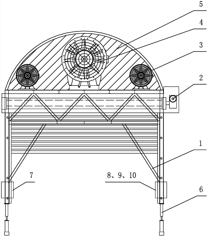
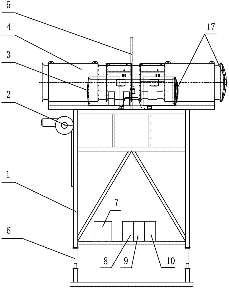
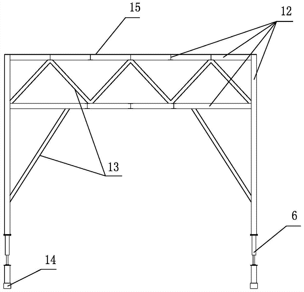
[0035] The present invention is a rapid ventilation and smoke exhaust device during the construction period of a long-distance tunnel, such as figure 1 with figure 2 As shown, it includes a gantry support 1, a fan unit and a damper group arranged on the gantry support 1, and a motor control system for respectively controlling the fan unit and the damper unit; as image 3 with Figure 4As shown, in this preferred example, the support platform and support column of the gantry support 1 welded with H-shaped I-steel 12 are used as an example for illustration, wherein the reinforcing bar 13 made of channel steel is used as a reinforced oblique support for the gantry support 1 to form a triangular Supporting structure; at the bottom of the supporting column of the gantry support 1, a connec...
PUM
 Abstract
Description
Claims
Application Information