Air source heat pump drying machine fully recycling exhaust waste heat

An air source heat pump and dryer technology, applied in the field of dryers, can solve the problems of non-recovery or less recovery of heat, the operating efficiency of the unit is not fully exerted, and the energy consumption is large, so as to achieve reasonable structure and solve high energy consumption. and pollution discharge problems, the effect of improving drying efficiency

Inactive Publication Date: 2015-04-08
合肥天鹅制冷科技有限公司
View PDF5 Cites 11 Cited by
  • Summary
  • Abstract
  • Description
  • Claims
  • Application Information

AI Technical Summary

Problems solved by technology

[0002] Drying exists in many fields, such as the drying of agricultural and sideline products, medicinal materials, tobacco, wood, and electroplated parts. At present, the traditional drying method consumes a lot of energy and causes pollution; even when the drying method of air source heat pump is used, due to the The hot air temperature provided is high (about 80°C), and the pressure ratio is usually large when using natural environmental heat sources for heating, so the efficiency of the unit is usually not high, and the heat is not recovered or recovered little during the dehumidification process (usually air-air heat Recycler, use the exhaust air to supplement the fresh air in the drying space for indirect heating, the actual heat recovery is very small), the drying speed is slow, and the operating efficiency of the unit has not been fully utilized

Method used


Image

  • Air source heat pump drying machine fully recycling exhaust waste heat
  • Air source heat pump drying machine fully recycling exhaust waste heat
  • Air source heat pump drying machine fully recycling exhaust waste heat

Examples


Embodiment Construction

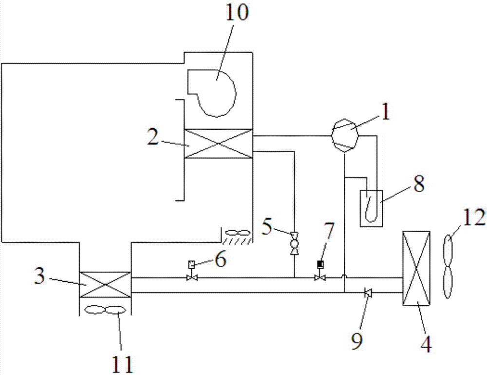
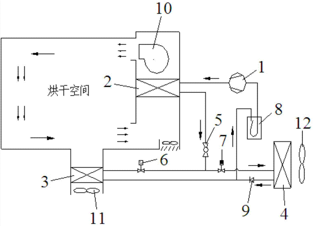
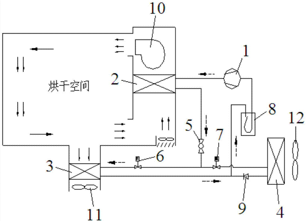
[0013] see figure 1 , an air source heat pump dryer that fully recovers exhaust waste heat, including a compressor 1, first and second internal air heat exchangers 2, 3, external air heat exchanger 4, expansion valve 5, first and second Solenoid valves 6, 7, one-way valve 9, gas-liquid separator 8, temperature and humidity sensing components and controller, the outlet of compressor 1 is connected to one side interface of the first internal air heat exchanger 2, the first internal The other side interface of the air heat exchanger 2 is connected with the expansion valve 5 and then divided into two branches, one of which is connected with the first electromagnetic valve 6 and the second internal air heat exchanger 3 in turn, and the other branch is It is connected with the second solenoid valve 7, the external air heat exchanger 4 and the one-way valve 9 in turn, and the ends of the two branches converge in one place and are connected with one end of the gas-liquid separator 8, ...


PUM


Abstract

The invention discloses an air source heat pump drying machine fully recycling exhaust waste heat. The air source heat pump drying machine fully recycling exhaust waste heat comprises a compressor, a first interior air heat exchanger, an exterior air heat exchanger, an expansion valve, a first electromagnetic valve, a second electromagnetic valve, a one-way valve, a gas-liquid separator, a temperature and moisture sensing component and a controller; an outlet of the compressor is connected with an interface on one side of the first interior air heat exchanger; an interface on the other side of the first interior air heat exchanger is divided into two branched circuits after being connected with the expansion valve; one branched circuit is sequentially connected with the first electromagnetic valve and the second interior air heat exchanger; the other branched circuit is sequentially connected with the second electromagnetic valve, the exterior air heat exchanger and the one-way valve; tail ends of the two branched circuits are gathered at the same position and are connected with one end of the gas-liquid separator; the other end of the gas-liquid separator is connected with an inlet of the compressor; the controller is electrically connected with the compressor, the expansion valve, the first electromagnetic valve, the second electromagnetic valve and the temperature and moisture sensing component. The air source heat pump drying machine fully recycling exhaust waste heat has the advantages of being energy saving, environment friendly and rapid.

Description

technical field [0001] The invention relates to the field of drying machines, in particular to an air source heat pump drying machine for fully recovering exhaust waste heat. Background technique [0002] Drying exists in many fields, such as the drying of agricultural and sideline products, medicinal materials, tobacco, wood, and electroplated parts. At present, the traditional drying method consumes a lot of energy and causes pollution; even when the drying method of air source heat pump is used, due to the The hot air temperature provided is high (about 80°C), and the pressure ratio is usually large when using natural environmental heat sources for heating, so the efficiency of the unit is usually not high, and the heat is not recovered or recovered little during the dehumidification process (usually air-air heat The recycler uses the exhaust air to supplement the fresh air in the drying space for indirect heating, and the actual heat recovery is very small), the dryi...

Claims


Application Information

Patent Timeline
Patent Type & Authority Applications(China)
IPC IPC(8): F26B21/00F26B25/00F24H4/06
CPCY02B30/52Y02P70/10
Inventor 陈斌郎群英程度煦汪长江赵贝
Owner 合肥天鹅制冷科技有限公司
Why Eureka
Try Eureka