Method for measuring underwater sound source low frequency radiation sound power in rectangular reverberation water tank arranged in air

A technology of radiated sound and internal measurement, which is applied in the direction of vibration measurement in fluids, measurement vibration, measurement devices, etc., can solve the problems of expansion, frequency domain without water tank application, etc., and achieve the effect of simple operation, low test cost and high efficiency

Active Publication Date: 2015-04-08
HARBIN ENG UNIV
View PDF2 Cites 20 Cited by
  • Summary
  • Abstract
  • Description
  • Claims
  • Application Information

AI Technical Summary

Problems solved by technology

Since then, the research on the use of reverberation water tanks to measure the sound power of sound sources was limited to the measurement of the sound radiation characteristics of different complex sound sources under the conditions of reverberation, and did not expand the application frequency domain of water tanks to low frequencies; until Tang Rui studied The sound field and free field of the reverberation tank have inherent transfer characteristics that are independent of the characteristics of the sound source, which greatly expands the frequency application range of the reverberation tank to low frequencies (Tang Rui. Low-frequency acoustic

Method used


Image

  • Method for measuring underwater sound source low frequency radiation sound power in rectangular reverberation water tank arranged in air
  • Method for measuring underwater sound source low frequency radiation sound power in rectangular reverberation water tank arranged in air
  • Method for measuring underwater sound source low frequency radiation sound power in rectangular reverberation water tank arranged in air

Examples


Embodiment Construction

[0019] The present invention will be further described below in conjunction with the accompanying drawings.

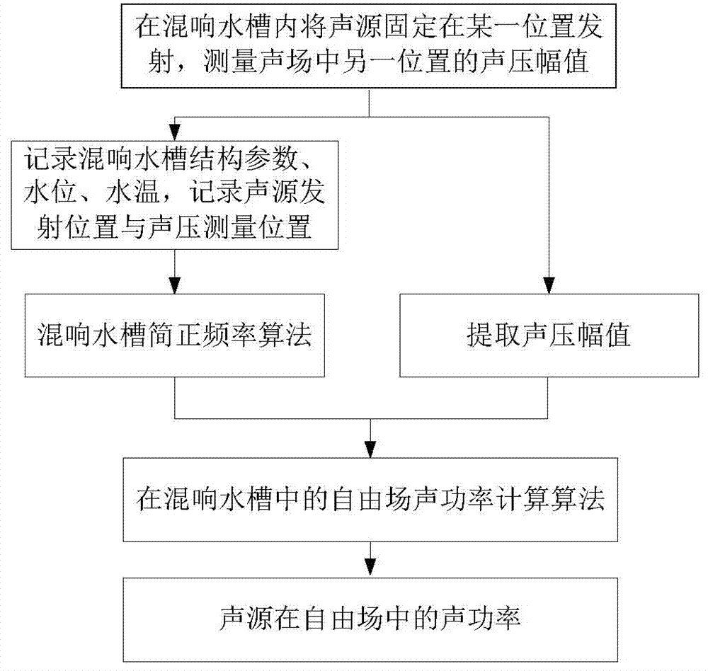
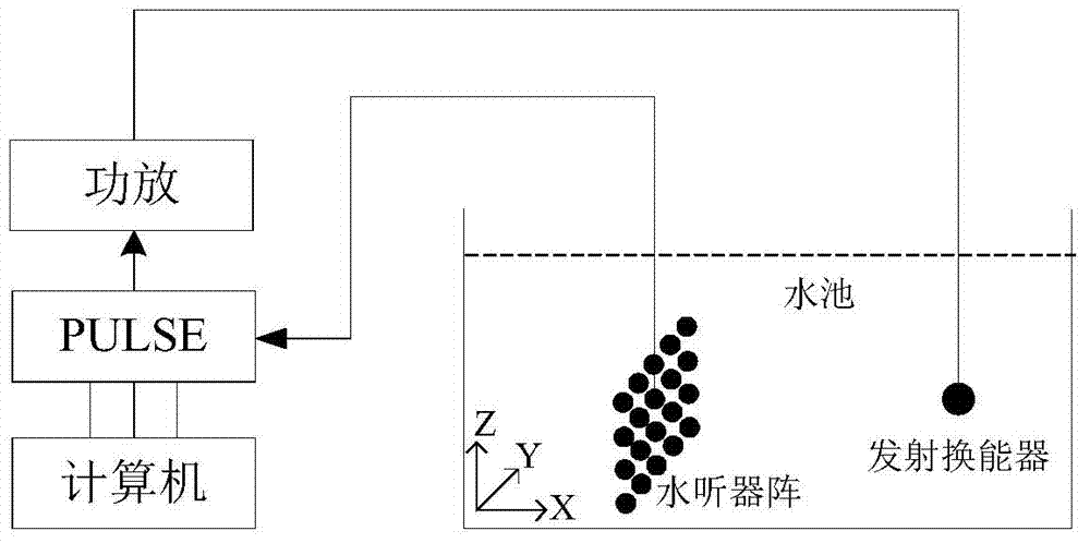
[0020] The method for measuring the low-frequency sound power of a sound source in a rectangular reverberation tank placed in the air of the present invention comprises the following steps, such as figure 1 Show:

[0021] (1) In the reverberation tank, the experiment measures the sound pressure amplitude received by the hydrophone at another fixed position when the sound source is emitted at a fixed position. In the sound field area far away from the tank boundary, that is, the transmitting transducer is placed in the area where the distance between the radiating surface and the tank wall and the water surface is greater than the maximum line of the transmitting transducer structure, and the hydrophone is placed where the distance between the receiving surface and the tank wall and the water surface is greater than In the area of ​​the maximum linearity of the hydroph...


PUM


Abstract

The invention relates to a method for measuring sound source radiation sound power and particularly relates to a method for measuring underwater sound source low frequency radiation sound power in a rectangular reverberation water tank arranged in the air. The method comprises steps that, a sound source is fixed at a position of a reverberation water tank for emission, and a hydrophone is fixed at another position to measure a sound pressure amplitude of the reception position; a reverberation water tank normal frequency calculation algorithm taking consideration of influence of a water tank wall structure on a sound field is employed, each-order normal frequency of the measurement water tank sound field is determined; the sound pressure amplitude measured in the step (1) and the water tank sound field normal frequency determined in the step (2) are taken as input parameters, the algorithm calculating the free field sound power in the reverberation water tank is employed, and the sound power of a to-be-measured sound source in the free field is determined. The method does not need to utilize a known sound source to carry out correction on the reverberation water tank sound field. When the sound field normal frequency in the water tank and the speed potential function are determined, influence of the water tank wall structure on the sound field is considered, so the sound field calculation result in the water tank is more accurate.

Description

technical field [0001] The invention relates to a method for measuring the radiated sound power of a sound source, in particular to a method for measuring the low-frequency sound power of an underwater sound source in a rectangular reverberation tank placed in the air. Background technique [0002] The main applications for measuring the radiated sound power of underwater sound sources are: noise evaluation and control of underwater vehicles such as submarines and torpedoes; noise evaluation and control of underwater operating equipment; sound source level calibration of underwater acoustic transducers Wait. Compared with the free field test, measuring the radiated sound power of the sound source in the reverberation tank has the advantages of simple operation, high test signal-to-noise ratio, and good measurement repeatability. Since there are few normal modes and uneven sound field distribution in the low-frequency domain of the tank, the low-frequency application of the ...

Claims


Application Information

Patent Timeline
IPC IPC(8): G01H3/10
Inventor 李琪唐锐尚大晶刘永伟
Owner HARBIN ENG UNIV
Why Eureka
Try Eureka