Electric-control drawing force detector

A technology of pulling force and detector, which is applied in the field of precision parts detection and can solve problems such as inability to provide

Inactive Publication Date: 2015-04-08
SHENZHEN POLYTECHNIC
View PDF8 Cites 10 Cited by
  • Summary
  • Abstract
  • Description
  • Claims
  • Application Information

AI Technical Summary

Problems solved by technology

[0006] What the present invention aims to solve is the problem that the drawing force detector in the prior art cannot provide the change data of the force in the whole drawing process and lacks

Method used


Image

  • Electric-control drawing force detector
  • Electric-control drawing force detector
  • Electric-control drawing force detector

Examples


Embodiment 1

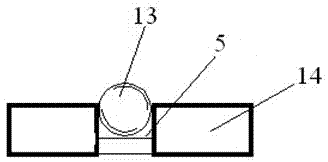
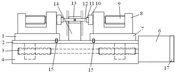
[0044] The electronically controlled pullout force detector in the present embodiment is as figure 1 and figure 2 As shown, it includes a base 4 and a slide rail 2 installed on the base 4 . Two sliding tables are installed on the slide rail 2, which are respectively a left sliding table 1 and a right sliding table 7, and a measuring head seat 8 is respectively installed on the left sliding table 1 and the right sliding table 7, and the two Each of the probe bases 8 is respectively clamped in the probe base positioning grooves on the left slide 1 and the right slide 7; each probe base 8 is provided with a detection ferrule 12. The clamping head 10 and the force sensor 9, wherein the detection ferrule 12 is fastened and fixed on one side of the clamping head 10 by a locking screw 11, and the other side of the clamping head 10 is connected to the The force sensor 9 is connected, and the clamping head 10 is also floatingly connected with the probe base 8; the detection ferrules...

Embodiment 2

[0061] The electronically controlled pullout force detector in the present embodiment is as figure 1 and figure 2 As shown, it includes a base 4 and a slide rail 2 installed on the base 4 . Two sliding tables are installed on the slide rail 2, which are respectively a left sliding table 1 and a right sliding table 7, and a measuring head seat 8 is respectively installed on the left sliding table 1 and the right sliding table 7, and the two Each of the probe bases 8 is respectively clamped in the probe base positioning grooves on the left slide 1 and the right slide 7; each probe base 8 is provided with a detection ferrule 12. The clamping head 10 and the force sensor 9, wherein the detection ferrule 12 is fastened and fixed on one side of the clamping head 10 by a locking screw 11, and the other side of the clamping head 10 is connected to the The force sensor 9 is connected, and the clamping head 10 is also floatingly connected with the probe base 8; the detection ferrule...


PUM


Abstract

The invention provides an electric-control drawing force detector which is provided with optoelectronic switches including two limiting optoelectronic switches respectively arranged on limiting positions of opposite movement of two sliding tables, and a zero point optoelectronic switch arranged on a zero rotation position of a rotating shaft of a stepping motor. According to the electric-control drawing force detector provided by the invention, the optoelectronic switches are arranged for determining the limiting positions of opposite movement of two sliding tables and the zero rotation position of the rotating shaft of the stepping motor, so that the stepping motor drives the sliding tables and a detection insertion core to move face to face or opposite to each other; in the operation process, the electric-control drawing force detector is inserted into two ends of a to-be-tested ceramic sleeve, and then is pulled outwards, during the process, a drawing force acquisition unit collects data information transmitted by a force sensor, and an arithmetic unit is used for calculating data information. With the adoption of the electric-control drawing force detector, recording and analysis on variation data of force during the whole pulling process are realized, and valuable reference basis is provided for improving production technologies such as parameter adjustment of production equipment, improvement of good-grade rate, reduction of rework rate and rejection rate.

Description

technical field [0001] The invention belongs to the technical field of precision parts detection, and in particular relates to an electronically controlled pulling force detector and a control method. Background technique [0002] The precision sleeve involved in the present invention belongs to the optical fiber connector. The optical fiber connector is a device for detachable (movable) connection between the optical fiber and the optical fiber. The energy can be coupled into the receiving optical fiber to the greatest extent, and the impact on the system caused by its intervention in the optical link is minimized. There are many types of fiber optic connectors, which can be divided into FC, SC, ST, MU, LC, etc. according to the connection method; according to the casing material, they can be divided into zirconia ceramic materials, SUS materials, glass materials, plastic materials, metal materials, etc. [0003] With the breakthrough and maturity of the most cutting-edge ...

Claims


Application Information

Patent Timeline
IPC IPC(8): G01N3/02G01N3/04G01N3/08
Inventor 陈红文励洪张磊
Owner SHENZHEN POLYTECHNIC
Why Eureka
Try Eureka