a measure of co 2 Device and working method of diffusion coefficient in the process of diffusion from water phase to oil phase

A diffusion device and diffusion process technology, applied in the direction of measuring devices, surface/boundary effects, instruments, etc., can solve the problems of oil-gas-water density difference and the inability to measure the diffusion coefficient, etc.

Active Publication Date: 2017-01-11
CHINA UNIV OF PETROLEUM (EAST CHINA)
View PDF1 Cites 0 Cited by
  • Summary
  • Abstract
  • Description
  • Claims
  • Application Information

AI Technical Summary

Problems solved by technology

These methods and devices can only measure CO 2 - Crude oil system or CO 2 - Diffusion coefficient of water system, CO has not been studied so far 2 The device of the diffusion coefficient from the water phase to the oil phase, and due to the existence of the density difference between oil, gas and water, in principle, the straight cylinder PVT method cannot measure CO 2 Diffusion coefficient in the process of diffusion from water phase to oil phase

Method used


Image

  • a measure of co  <sub>2</sub> Device and working method of diffusion coefficient in the process of diffusion from water phase to oil phase
  • a measure of co  <sub>2</sub> Device and working method of diffusion coefficient in the process of diffusion from water phase to oil phase
  • a measure of co  <sub>2</sub> Device and working method of diffusion coefficient in the process of diffusion from water phase to oil phase

Examples


Embodiment 1

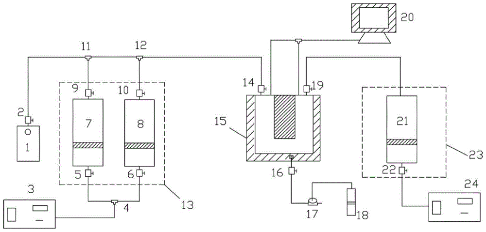
[0097] A measure of CO 2 The device for the diffusion coefficient in the process of diffusion from the water phase to the oil phase, including the CO pipes connected vertically and side by side in sequence 2 Gas source, distilled water source, U-shaped high-temperature and high-pressure visible diffusion device 15, and crude oil source, and a steel body partition 41 is vertically arranged in the U-shaped high-temperature and high-pressure visible diffusion device 15, and the steel body partition 41 divides the The U-shaped high-temperature, high-pressure visible diffusion device 15 is divided into a left space 35 and a right-side space 40 connected at the bottom, and the bottom of the U-shaped high-temperature, high-pressure visible diffusion device 15 is provided with a temperature measuring point 42, a pressure measuring point 43, Lower exit 46, the CO 2 The gas source and the distilled water source are respectively communicated with the left side space 35 through pipelines...

Embodiment 2

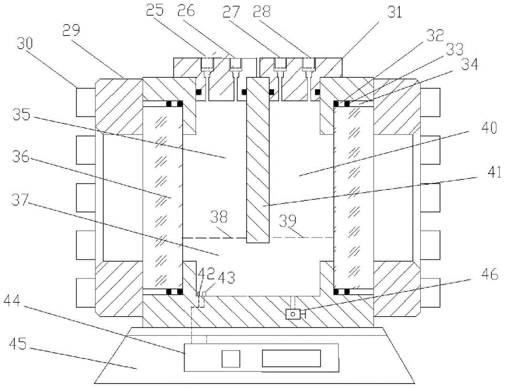
[0100] According to the device described in Embodiment 1, the difference is that a base 45 is provided at the bottom of the U-shaped high temperature and high pressure visible diffusion device 15 , and the temperature control system 44 is provided on the base 45 .

Embodiment 3

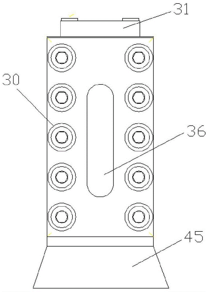
[0102] According to the device described in embodiment 1 or 2, the difference is that the two sides of the U-shaped high-temperature and high-pressure visible diffusion device 15 are provided with a pressure-bearing visible glass 36 and a stainless and corrosion-resistant steel body 29. The pressure-bearing visible glass 36 is embedded in the stainless and corrosion-resistant steel body 29, and the middle pressure pad 32, O-ring 33, and upper pressure pad 34 seal the pressure-bearing visible glass 36 and the stainless and corrosion-resistant steel body 29. The annular gap between the steel bodies 29; the stainless and corrosion-resistant steel body 29 has a temperature resistance of 150° C. and a pressure resistance of 32 MPa; the pressure resistance of the middle pressure pad 32 , O-ring 33 and upper pressure pad 34 is 25 MPa.

[0103] The advantage of the design here is that the pressure-bearing sight glass 36 can objectively and truly observe the change of the liquid level d...


PUM


Abstract

The invention relates to a device for measuring the diffusion coefficient of CO2 in the process of diffusing CO2 from a water phase to an oil phase. The high-temperature and high-pressure visible diffusion device is vertically provided with a steel body partition, which divides the U-shaped high-temperature and high-pressure visible diffusion device into a left space and a right-side space connected at the bottom. The U-shaped high-temperature and high-pressure visible diffusion device The inner bottom is provided with a temperature measurement point, a pressure measurement point, and a lower outlet. The device also includes a pressure acquisition system, a back pressure gas tank, a heater, and a temperature control system. The principle of the invention is reliable, the operation is simple, and the influence caused by the difference in the density of oil, gas, and water is overcome. , the pressure drop method for measuring the gas-liquid two-phase diffusion coefficient is applied to the measurement of the gas diffusion coefficient between the water phase and the oil phase.

Description

technical field [0001] The invention relates to a method for measuring CO 2 The device and working method of the diffusion coefficient in the process of diffusing from the water phase to the oil phase belong to the technical field of petrochemical industry. Background technique [0002] CO 2 -Water alternating injection flooding technology is the most commonly used CO2 at home and abroad 2 Oil flooding technology. This technology has a good application prospect in enhancing oil recovery; at the same time, CO 2 As the main greenhouse gas, accounting for more than two-thirds of the total greenhouse gas, CO 2 Oil flooding technology is one of the effective ways to reduce greenhouse gas emissions. Therefore, the above-mentioned technologies have been widely valued by countries all over the world due to their advantages such as high oil displacement efficiency, wide application range, and reduced greenhouse effect. [0003] Formation temperature and pressure, CO 2 Soluble ...

Claims


Application Information

Patent Timeline
Patent Type & Authority Patents(China)
IPC IPC(8): G01N13/00
Inventor 李宾飞叶金桥李兆敏张继国李松岩丁立苹
Owner CHINA UNIV OF PETROLEUM (EAST CHINA)
Why Eureka
Try Eureka