Low-power four-phase switched reluctance generator power converter

A technology for reluctance generators and power converters, applied in the direction of controlling generators through magnetic field changes, controlling generators, synchronous generators, etc., can solve the problems of increasing filter pressure and maintenance costs, large output voltage and current fluctuations, The voltage cannot be adjusted online, etc., to achieve the effect of increasing the output power density and total power, low output voltage and current, and less total power

Inactive Publication Date: 2015-04-08
CHINA JILIANG UNIV
View PDF6 Cites 12 Cited by
  • Summary
  • Abstract
  • Description
  • Claims
  • Application Information

AI Technical Summary

Problems solved by technology

[0003] The working process of the switched reluctance generator is divided into two stages of excitation and power generation, and it is carried out in time-sharing. The excitation method is divided into separate excitation and self-excitation. The separate excitation method realizes independent circuits for excitation and power generation, and has high reliability. However, a special battery or other DC power supply is generally required as the excitation power supply. The self-excitation method does not require external power supply, but the output voltage and current fluctuate greatly, causing greater pressure on the filter.
[0004] In view of the fact that increasing the excitation voltage is conducive to increasing the winding current during subsequent freewheeling power generation and thus increasing the output power, and to change the problem that the traditional excitation voltage cannot be adjusted online, some new types of excitation input voltages that can be adjusted online according to the requirements of the control system have emerged in recent years. The circuit structure of the excitation part of the power converter, such as: 1. Peng Hanmei, Yi Lingzhi, etc. New excitation mode of switched reluctance generator based on Buck converter [J]. Solar Energy Sinica, 2012, 33(3). 2. Duan Lihua. Research on the hardware structure of offshore drilling platform wind power generation system based on variable power converters[J]. Ship Electric Technology, 2012, 32(2). The former has a relatively unidirectional change in excitation voltage and output power generation voltage and current fluctuations The biggest disadvantage is that the latter must be equipped with a dedicated excitation power supply, which increases the filter pressure and maintenance costs

Method used


Image

  • Low-power four-phase switched reluctance generator power converter
  • Low-power four-phase switched reluctance generator power converter

Examples


Embodiment Construction

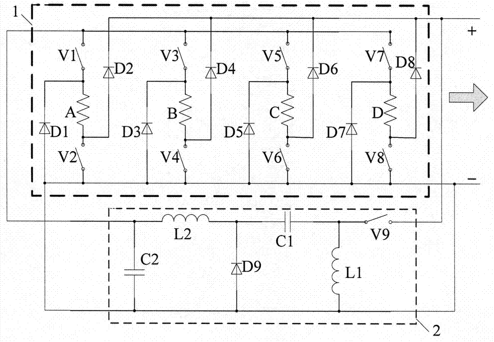
[0018] attached figure 1 It is the main circuit of the low-power four-phase switched reluctance generator power converter of the present invention, and the A, B, C, D four-phase windings are the center to form a separately excited asymmetric half bridge according to the asymmetric half bridge type and the traditional separately excited mode. The four-phase winding power converter main circuit 1, the excitation part is completed by the Zeta chopper circuit 2 alone.

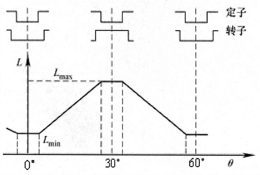
[0019] In this embodiment, the switched reluctance generator is selected as a four-phase 8 / 6-pole structure, that is, a low-power switched reluctance generator with 8 poles in the stator and 6 poles in the rotor. The relationship between the inductance of the stator winding and the position angle of the rotor is as follows figure 2 Shown; at the origin position of 0°, the minimum inductance is L min , at this time the stator salient pole coincides with the centerline of the rotor groove, at 30°, the air gap betwe...


PUM


Abstract

The invention discloses a low-power four-phase switched reluctance generator power converter. A main circuit of the converter consists of a separately excited asymmetric half-bridge four-phase winding power converter main circuit and a Zeta chopper circuit which are in end-to-end connection in parallel; a generation output side of the separately excited asymmetric half-bridge four-phase winding power converter main circuit is in parallel connection with an input side of the Zeta chopper circuit; and an output side of the Zeta chopper circuit is in parallel connection with an excitation input side of the separately excited asymmetric half-bridge four-phase winding power converter main circuit. The converter has a simple structure, two windings can work at the same time, so that power density is increased, the voltage and current pulsation is reduced, the wide adjustable range of the exciting voltage is beneficial to the control of the maximum power output, and the converter can be used in the fields of small-scale wind power generation and direct current power supply.

Description

technical field [0001] The invention relates to the field of motor control, in particular to a power converter of a low-power four-phase winding switched reluctance generator and its control. Background technique [0002] Switched Reluctance Generator (Switched Reluctance Generator, referred to as: SRG) has a simple structure, no brush, no winding, no permanent magnet on the rotor; within a certain speed range, the output terminal voltage will not change with the speed change, very suitable for It is used for wind power generation and as a DC power supply; during operation, the switched reluctance generator has many controllable parameters, such as switching angle control, current chopping control, PWM control, etc., which can easily realize more complex control strategies and is flexible The control output DC voltage and current. [0003] The working process of the switched reluctance generator is divided into two stages of excitation and power generation, and it is carrie...

Claims


Application Information

Patent Timeline
Patent Type & Authority Applications(China)
IPC IPC(8): H02P9/00H02P103/20
CPCH02P9/30
Inventor 孙冠群
Owner CHINA JILIANG UNIV
Why Eureka
Try Eureka