Novel filter tank

A filter tank, a new type of technology, applied in the direction of filtration separation, gravity filter, loose filter material filter, etc., can solve the problems of small filter area, easy hardening of filter material, easy mixing layer of filter material, etc., to extend the filtration cycle , The effect of increasing the dirt holding capacity and increasing the filtration area

Inactive Publication Date: 2015-04-15
QINGDAO GUANDA TRADE
View PDF0 Cites 2 Cited by
  • Summary
  • Abstract
  • Description
  • Claims
  • Application Information

AI Technical Summary

Problems solved by technology

[0003] Most of the traditional filter tanks are arranged vertically. On the one hand, this kind of vertical filter tank has small filtration area, low filtration rate and large volume; in addition, it requires a lot of space for installation, and there are many inconveniences.
[0004] Currently used filter devices, one type uses sand and gravel filter materials, such as quartz sand, anthracite, magnetite, etc. The filter materials used in this type of filter device are cheap and easy to obtain, easy to clean and regenerate, and the cost is low, but there are filter materials. The disadvantages are low speed, high backwashing intensity, and easy mixing of filter materials after backwashing; the other type is to use fiber filter materials, such as fiber ball high-speed filter devices and long-fiber filter devices. It solves the above-mentioned problems of low filtration rate, high backwash intensity, and mixed layers of filter material after backwash, but there are also problems such as high cost, short service life, easy hardening of filter material, and difficulty in cleaning and regeneration.
[0005] The method of backwashing is controlled by the pressure difference between the inlet and outlet of the filter tank. When the filter material or filter medium changes, the corresponding relationship between the filter speed and the pressure difference will also change accordingly. The filter speed cannot be accurately controlled, nor can it Accurately control filtration cycle and backwash intensity

Method used


Image

  • Novel filter tank
  • Novel filter tank

Examples


Embodiment Construction

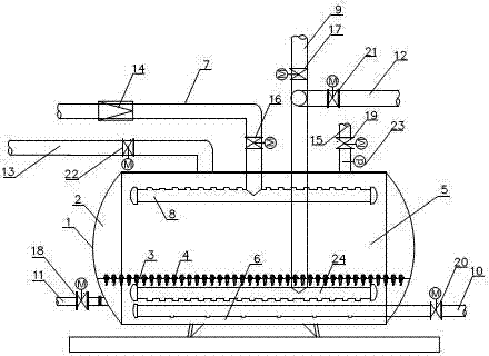
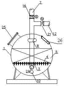
[0027] like figure 1 and figure 2 As shown, the tank body 1 is arranged horizontally, with heads 2 provided at both ends, and a manhole 25 and an observation hole 26 are arranged on the side of the tank body 1. On the upper part of the tank body 1, the water inlet pipe flowmeter 14 and the The water pipe electric valve 16 is arranged on the water inlet pipe 7 . The inside of the filter tank is provided with a water distribution pipe 8, the water distribution pipe 8 is provided with a water distribution pipe orifice, and the water distribution pipe orifice is opened upwards. In the upper part of the tank, a water collection pipe 24 is also provided inside the filter tank. The water pipe 24 is provided with a water collection pipe aperture, and the water collection pipe aperture downwards offers, and in the bottom in the tank, the water distribution pipe 8 links to each other with the water inlet pipe 7. The filter plate 3 divides the filter tank into an upper filter area and...


PUM


Abstract

The invention relates to a novel filter tank which comprises a tank body, a water collection pipe and a water distribution pipe. A water inlet pipe, a water outlet pipe, an air outlet pipe and a back wash water drainage pipe are arranged on the tank body. A manhole and an observation hole are arranged on the lateral side of the tank body. The water distribution pipe is arranged on the upper portion of the interior of the tank body and connected with the water inlet pipe. Orifices are arranged upwards. A back wash water inlet is arranged on the water drainage pipe. A blow-down pipe is arranged at the lower part of the tank body. An air inlet pipe is arranged on the bottom of the interior of the tank body. The water collection pipe is arranged above the air inlet pipe and connected with the water outlet pipe. A filter plate is arranged between the water distribution pipe and the water collection pipe. A material filtering layer is arranged above the filter plate. A flowmeter and an electrically operated valve of the water inlet pipe are arranged on the water inlet pipe. The novel filter tank adopts the arrangement of reversed graded filter materials. Filter materials of a large grain size and a large proportion are kept at the bottom of the tank body and can be automatically graded after back wash.

Description

technical field [0001] The invention relates to a filter device, in particular to a novel filter tank. Background technique [0002] The filter tank is a device for filtering under the action of pressure. It mostly adopts a vertical structure. According to the pressure difference between the inlet and outlet of the filter device, the filter material is backwashed to clean the impurities contained in the filter material layer, so as to maintain the filtration efficiency. Good filtration performance and water quality of filtered water. [0003] Most of the traditional filter tanks are arranged vertically. On the one hand, this kind of vertical filter tank has small filtration area, low filtration rate and large volume; in addition, it requires a lot of space for installation, which is inconvenient. [0004] Currently used filter devices, one type uses sand and gravel filter materials, such as quartz sand, anthracite, magnetite, etc. The filter materials used in this type of ...

Claims


Application Information

Patent Timeline
Patent Type & Authority Applications(China)
IPC IPC(8): B01D24/14B01D24/12B01D24/46
Inventor 周君祥
Owner QINGDAO GUANDA TRADE
Why Eureka
Try Eureka