Method and device for fast detection of line current fault

A technology of line current and detection device, applied in directions such as fault location, can solve the problems of large delay of transmission signal and affect fast protection action, and achieve the effect of ensuring safety

Active Publication Date: 2017-08-25
XUJI GRP +1
View PDF5 Cites 0 Cited by
  • Summary
  • Abstract
  • Description
  • Claims
  • Application Information

AI Technical Summary

Problems solved by technology

[0003] The purpose of the present invention is to provide a method and device for fast detection of line current faults, which are used to solve the problem that the transmission signal delay of the traditional DC transmission line fault detection device is relatively large, which affects the fast protection action

Method used


Image

  • Method and device for fast detection of line current fault
  • Method and device for fast detection of line current fault
  • Method and device for fast detection of line current fault

Examples


Embodiment Construction

[0013] The present invention will be described in further detail below in conjunction with the accompanying drawings.

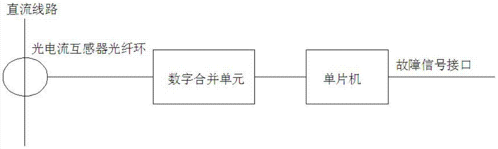
[0014] A method for quickly detecting line current faults comprises: a photocurrent sensor collects line current signals, and transmits the line current signals to a digital merging unit, and the digital merging unit transmits the processed line current signals to a single-chip microcomputer.

[0015] A line current fault fast detection device, comprising a photocurrent sensor, a digital merging unit, and a single-chip microcomputer; the output end of the photocurrent sensor is connected to the corresponding input end of the digital merging unit, and the output end of the digital merging unit is connected to the corresponding input end of the single-chip microcomputer.

[0016] Based on the above technical solutions and in conjunction with the accompanying drawings, the following specific implementation is given.

[0017] The photocurrent sensor and single-ch...


PUM


Abstract

The invention provides a rapid line current fault detection method and a rapid line current fault detection device. The rapid line current fault detection method includes that an optical current sensor acquires line current signals and transmits the line current signals to a digital merging unit, the digital merging unit transmits processed line current signals to a single chip microcomputer, and the single chip microcomputer completes fault detection. The rapid line current fault detection device comprises the optical current sensor, the digital merging unit and the single chip microcomputer. The rapid line current fault detection device can detect line faults rapidly and output fault signals within 100us, thereby being particularly applicable to a flexible direct-current power transmission system consisting of IGBTs (insulated gate bipolar translators) and used for rapid main protection of converter valve overcurrent faults or rapid protection of line overcurrent faults.

Description

technical field [0001] The invention relates to a method and device for quickly detecting line current faults, belonging to the technical field of high-voltage direct current transmission. Background technique [0002] At present, the traditional DC transmission line fault detection device is limited by the current sensor and the performance of the merging unit. The delay after the merging unit processes the optical signal is relatively large, usually about 100us, and the output data signal after the merging unit processes the optical signal The frame transmission rate is only 10kHZ. In this way, the delay of signal transmission to the microcontroller is at least 200us, which is far from meeting the requirements of the converter valve or line overcurrent fault in the flexible direct current transmission system composed of IGBTs. The fast protection action of less than 100us requirements. Contents of the invention [0003] The purpose of the present invention is to provide...

Claims


Application Information

Patent Timeline
Patent Type & Authority Patents(China)
IPC IPC(8): G01R31/08
Inventor 张建何青连范彩云李生林张志刚洪波
Owner XUJI GRP
Why Eureka
Try Eureka