Charged particle radiation device
A technology of charged particle lines and charged particles, applied in circuits, discharge tubes, electrical components, etc., can solve problems such as state changes, damage to biochemical samples and liquid samples, etc.
- Summary
- Abstract
- Description
- Claims
- Application Information
AI Technical Summary
Problems solved by technology
Method used
Image
Examples
Embodiment 1
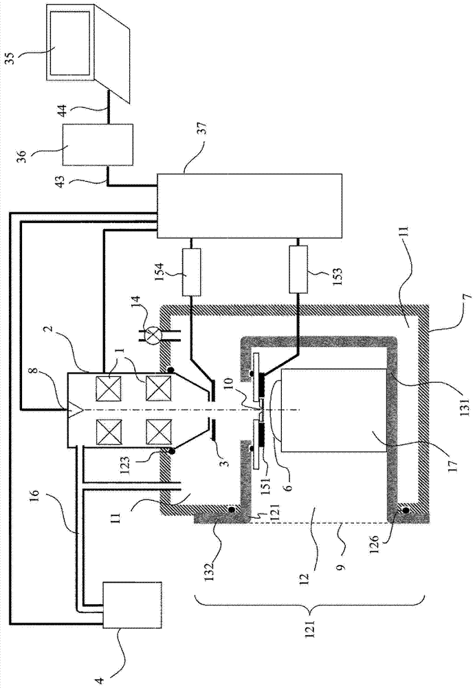
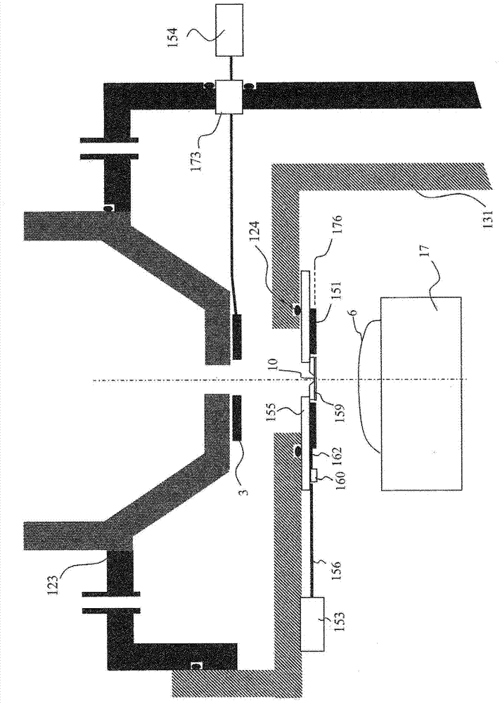
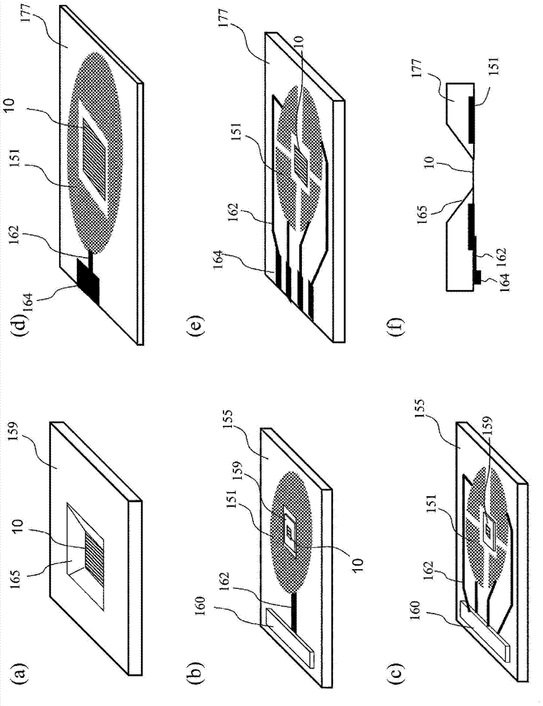
[0032] In this embodiment, a basic embodiment will be described. exist figure 1 The diagram of the overall configuration of the charged particle microscope of this embodiment is shown in . figure 1 The charged particle microscope shown in is mainly composed of a charged particle optical column 2, a first case 7 (hereinafter also referred to as a vacuum chamber) supporting the charged particle optical column with respect to the installation surface of the device, and a second case inserted into the first case 7 and used. Two cabinets 121 (hereinafter also referred to as accessories) and a control system for controlling these devices are constituted. When the charged particle microscope is in use, the inside of the charged particle optical column 2 and the first cabinet is evacuated by a vacuum pump 4 . The start and stop actions of the vacuum pump 4 are also controlled by the control system. In the figure, only one vacuum pump 4 is shown, and there may be more than two vacuu...
Embodiment 2
[0064] In this example, other application examples of the charged particle microscope will be described. Furthermore, specific examples of charged particle microscopes include scanning electron microscopes, ion microscopes, and the like. In the following, descriptions of the same parts as those in Embodiment 1 are omitted.
[0065] exist Figure 5 The diagram of the overall configuration of the charged particle microscope of this embodiment is shown in . Similar to Embodiment 1, the charged particle microscope of this embodiment is also composed of a charged particle optical column 2, a first cabinet (vacuum chamber) 7 that supports the charged particle optical column with respect to the installation surface of the device, inserted into the first cabinet 7, and used. The second cabinet (accessory) 121, the control system and the like are formed. The actions and functions of these elements or additional elements added to each element are almost the same as those in Embodimen...
Embodiment 3
[0089] In this example, regarding the Figure 5 A configuration example in which the cover member 122 is removed from the device configuration will be described. In the following, descriptions of the same parts as those in Embodiments 1 and 2 are omitted.
[0090] exist Figure 8 , shows the overall configuration of the charged particle microscope of this embodiment. As for the control system, since it is the same as that of the second embodiment, illustration is omitted, and only important parts of the device are shown.
[0091] exist Figure 8 In the shown structure, the sample workbench 5 is directly fixed on the bottom surface of the second cabinet 121 . The gas supply pipe 100 may also be fixed on the second cabinet 121, or may not be fixed. According to this structure, since the sample is allowed to protrude from the outside of the device, it is possible to observe a sample having a larger size than the structure of Example 2 including the cover member 122 .
PUM
 Abstract
Description
Claims
Application Information
 - R&D
- Intellectual Property
- Life Sciences
- Materials
- Tech Scout
- Unparalleled Data Quality
- Higher Quality Content
- 60% Fewer Hallucinations
Browse by: Latest US Patents, China's latest patents, Technical Efficacy Thesaurus, Application Domain, Technology Topic, Popular Technical Reports.
© 2025 PatSnap. All rights reserved.Legal|Privacy policy|Modern Slavery Act Transparency Statement|Sitemap|About US| Contact US: help@patsnap.com


