A high-pressure-resistant separation filtration membrane column device with a low-resistance deflector

A technology of separation and filtration and high pressure resistance, which is applied in the fields of semi-permeable membrane separation, membrane technology, osmosis/dialysis water/sewage treatment, etc. It can solve the problems of failure of filtration effect, deformation, damage and deterioration of lip seal ring, etc., to reduce the occurrence of Risk of displacement, reduced chance of liquid leakage, effect of reduced resistance loss

Active Publication Date: 2016-08-24
浙江美易膜科技有限公司
View PDF2 Cites 0 Cited by
  • Summary
  • Abstract
  • Description
  • Claims
  • Application Information

AI Technical Summary

Problems solved by technology

[0005] 1. Only relying on the two nuts at both ends of the center tie rod to provide pre-tightening force to the flange and membrane stack in the shell, the force is not enough, especially in the actual operation process when the inlet water pressure increases above 70bar, the terminal Leakage often occurs around the connecting flange and the bottom flange, and even the lip seal is pressed out of the device, resulting in deformation and damage to the lip seal, making the equipment unable to work normally
Furthermore, due to the low thermal conductivity of FRP, the use of FRP shells is not conducive to the transfer of heat brought in by the fluid to the outside. The diaphragm layer is operated under high temperature and high pressure, which is easily damaged and shortens the service life of the entire equipment.
[0006] 2. When the fluid flows through the diversion plate, it flows to and leaves the diversion hole in the center of the diversion plate, which makes the O-ring adjacent to the diversion hole bear the impact force from a range of 360 degrees, and is very prone to displacement
Once the O-ring here is displaced, the filtering effect of the equipment will be invalid
Moreover, finding and repairing the displaced O-ring is a very time-consuming and labor-intensive work, which seriously affects the practicability and marketing of the disc tube-membrane assembly in actual use.
[0007] 3. Every time the fluid passes through a deflector plate, it will be deflected twice at the flange of the deflector plate, resulting in a large resistance loss
As a result, the resistance loss of the entire equipment is relatively large, so that the inlet water has to be raised to a higher pressure, which increases the burden on the entire equipment and worsens the situation described in the disadvantages 1 and 2.
This subjects the surface of the membrane in contact with the top of the diversion bump to constant mechanical wear, leaving deep marks on the membrane that can puncture the membrane, causing the entire device to lose its filtering effect
This causes a greater risk of diaphragm punctures when the operating temperature is increased

Method used


Image

  • A high-pressure-resistant separation filtration membrane column device with a low-resistance deflector
  • A high-pressure-resistant separation filtration membrane column device with a low-resistance deflector
  • A high-pressure-resistant separation filtration membrane column device with a low-resistance deflector

Examples


Embodiment Construction

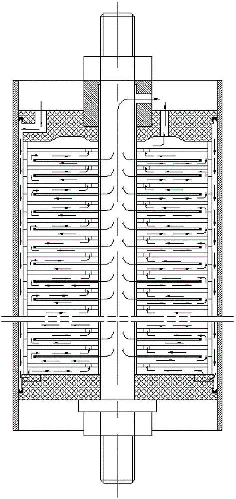
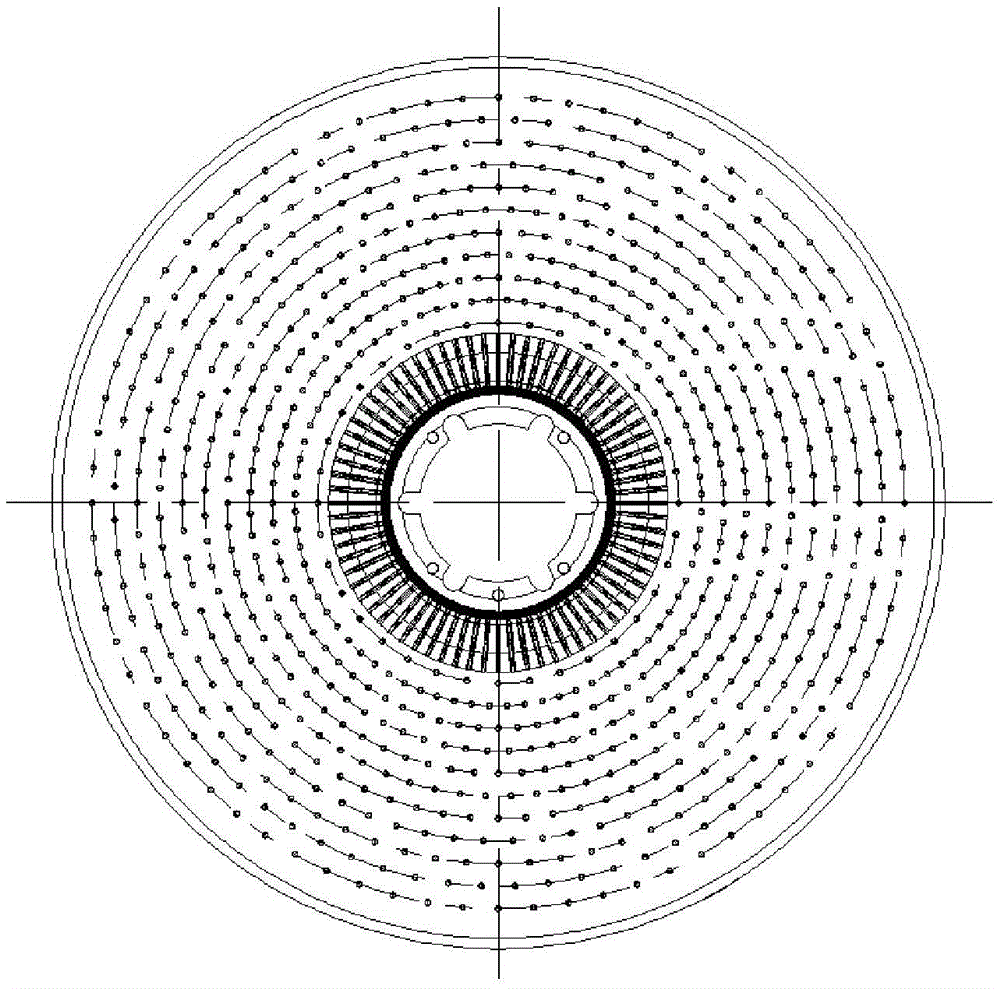
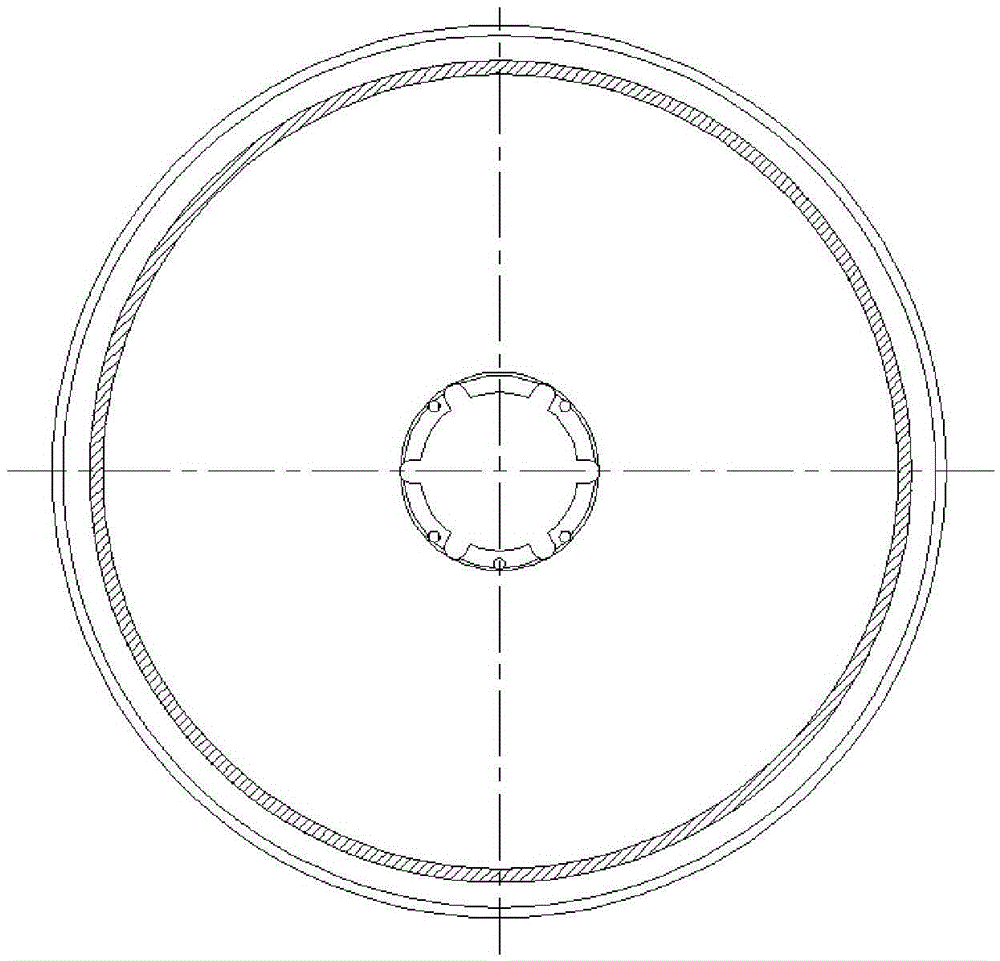
[0036] Such as Figure 4 , 5 As shown, a high-pressure separation filtration membrane column device with a low-resistance deflector plate includes a deflector plate 1, a diaphragm 2, and a circular tube-shaped pressure-bearing shell 3, and the two ends of the pressure-bearing shell 3 are flange structures.

[0037] The central opening of the guide plate 1 and the diaphragm 2, multiple guide plates 1 and diaphragms 2 are stacked alternately to form a membrane stack with a central opening, that is, the diaphragm 2 is sandwiched between two adjacent guide plates 1 , only without diaphragms on the deflectors at both ends. The outer diameter of the membrane stack is smaller than the inner diameter of the pressure housing 3, and the gap between them is the raw water channel 4 of the membrane column.

[0038] The two ends of the membrane stack are respectively provided with a terminal sealing plate 5 and a connecting end sealing plate 6. The central opening of the terminal sealing ...


PUM


Abstract

The invention relates to a low-resistance flow guide plate and high-pressure-resistant separation filtering membrane column device. Two ends of a pressure bearing outer shell of a membrane column provided by the invention are of flange structures; fixed compression rings and movable compression rings are fixedly connected with flanges at two ends of the membrane column via flange discs and bolts and nuts. Liquid reducing holes are formed in one sides of flow guide plates which form a membrane stack, and the other sides of the flow guide plates are provided with liquid receiving regions; the liquid receiving regions and the liquid reducing holes are the same in area; other regions of two surfaces of each flow guide plate, except for the liquid receiving regions, are provided with a plurality of flow guide salient points, and the flow guide salient points at two surfaces are corresponding in position. The pressure of a central pull rod and nuts at two ends of the central pull rod is relieved by the flange structures provided by the invention, and the membrane stack is compressed further, so that the whole membrane column can resist high pressure relatively well. A fluid flows from the liquid reducing holes to the liquid receiving regions of the next stage of flow guide plate, and then flows through two membrane surfaces of a membrane layer, leaves from the liquid reducing holes of the flow guide plates, and flows to the next stage of flow guide plate; baffling for twice when the fluid flows through the flow guide plates is prevented, and the resistance loss of the fluid while flowing through the flow guide plates is reduced.

Description

technical field [0001] The invention belongs to the technical field of membrane filtration, and in particular relates to a high-pressure-resistant separation filtration membrane column device with a low-resistance guide plate. Background technique [0002] Disc tube membrane assembly ( figure 1 ) is a great progress in the field of flat membrane module technology. The membrane module is a device that uses nanofiltration or reverse osmosis to filter and separate liquids. Due to the guide element with excellent hydrodynamic performance in the device, when the fluid flows in it, it has the characteristics of wide flow channel, short flow and full turbulence. These characteristics make the disc tube membrane module have the characteristics of low resistance and high anti-pollution compared with other membrane modules. It also operates cost-effectively at increased reverse osmosis turbidity and sludge density index (SDI). It has been successfully applied to the treatment proc...

Claims


Application Information

Patent Timeline
Patent Type & Authority Patents(China)
IPC IPC(8): B01D61/00B01D63/00C02F1/44
Inventor 陈楚龙杨柳青
Owner 浙江美易膜科技有限公司
Why Eureka
Try Eureka