
Electric smelting forming method for ultra-supercritical high intermediate pressure rotor

An ultra-supercritical, medium and high pressure technology, applied in welding equipment, metal processing equipment, manufacturing tools, etc., can solve the problems of lack of supporting equipment, late start and other problems, and achieve the effect of no macrosegregation, simplified processing procedures, and shortened product cycle.

Active Publication Date: 2015-04-22
NANFANG ADDITIVE MFG TECH
View PDF6 Cites 9 Cited by
  • Summary
  • Abstract
  • Description
  • Claims
  • Application Information

AI Technical Summary

Problems solved by technology

my country's supercritical technology started late. Although major domestic manufacturers have carried out a lot of technical research, the 12% Cr system high and medium pressure rotor as the core component is currently 12% Cr due to problems in the research and development of materials and the lack of corresponding supporting equipment. High and medium pressure rotors can only rely on imports

Method used


Image

  • Electric smelting forming method for ultra-supercritical high intermediate pressure rotor
  • Electric smelting forming method for ultra-supercritical high intermediate pressure rotor
  • Electric smelting forming method for ultra-supercritical high intermediate pressure rotor

Examples


Embodiment Construction

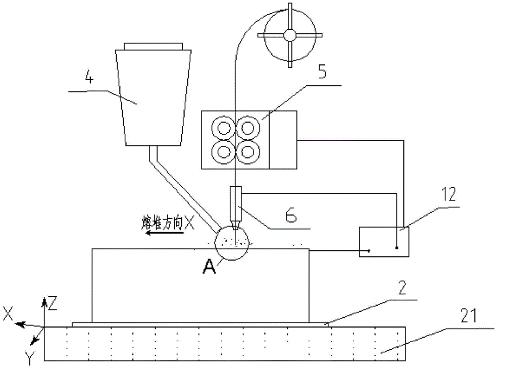
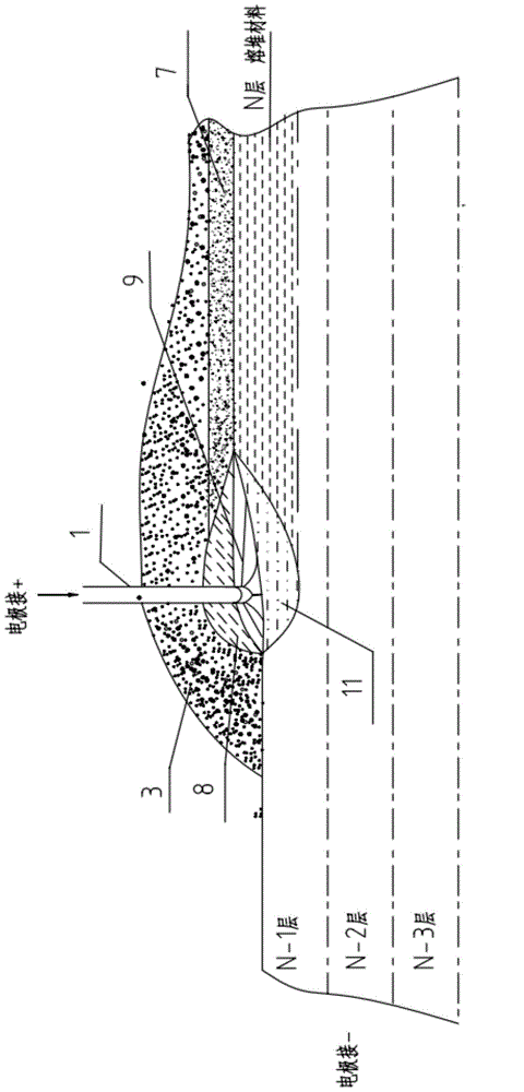
[0018] Specific embodiments of the present invention will be described below with reference to the accompanying drawings. Figure 1A An explanatory diagram of the principle of the metal component electrofusion forming method involved in this embodiment; Figure 1B It is a partial enlarged view. Since it is a schematic diagram, the components in the figure are schematic, and their actual shapes and dimensions are not limited by what is shown in the figure.

[0019] In this forming method, the raw wire material 1 is melted and deposited layer by layer (shown in FIG. 1 as the state when the Nth layer is deposited) on the base material 2, thereby finally forming a desired metal member.

[0020] The specific implementation process is:

[0021] A. The wire feeding mechanism 5 sends the raw material wire 1 to the surface of the base material 2 placed on the workbench 21 , which is covered with the granular auxiliary materials conveyed by the powder feeding mechanism 4 .

[0022] B....


PUM

PropertyMeasurementUnit
diameteraaaaaaaaaa
surface temperatureaaaaaaaaaa
lengthaaaaaaaaaa

Abstract

The invention provides an electric smelting forming method for an ultra-supercritical high intermediate pressure rotor. The method is efficient and low in cost and has the good mechanical property. The method comprises the steps that an electric smelting head and a base material are connected to two electrodes of a power source; in the forming process, metal raw material wires are conveyed to the surface of the base material through a conveying mechanism and the electric smelting head; under accumulation protection of granular auxiliary materials, an electric arc is generated between the raw material wires and the base material, and the auxiliary materials are accumulated and laid on a smelting portion to form a melting slag pool; currents flow through the raw material wires and the melting auxiliary material slag pool to form resistance heat and electric slag heat; under the effect of three heat composite high-energy heat sources of electric arc heat, resistance heat and electric slag heat, the raw material wires are smelted, and a local smelting pool is formed on the surface of the base material; the raw material wires and the auxiliary materials are continuously conveyed, and according to layered section data of a forming component, a computer is adopted to control relative moving between the electric smelting head and the base material; and rapid cooling layer-by-layer solidification accumulation of the smelting pools on the base material is achieved, and finally layer-by-layer accumulation is carried out to form a rotor component.

Description

technical field [0001] The invention relates to an electrofusion forming method for an ultra-supercritical high-medium-voltage rotor. Background technique [0002] The coal consumption of ultra-supercritical units for power generation is less than 300Kg / kwh, which is about 20g less coal per kilowatt-hour than subcritical units of the same capacity. Therefore, it is the main development direction of clean coal power generation technology in my country, and it is also a solution to the current power shortage and energy utilization. A realistic and effective approach to problems such as low environmental pollution and serious environmental pollution. [0003] Ultra-supercritical high and medium pressure rotors are alloy steel forgings that operate in high-temperature and high-pressure environments. The operating conditions are the most stringent, the safety requirements are the highest, and the product manufacturing is extremely difficult. Currently, only a few companies in Germ...

Claims


Application Information

Patent Timeline
Patent Type & Authority Applications(China)
IPC IPC(8): B23K28/02
CPCB22F3/105
Inventor 不公告发明人
Owner NANFANG ADDITIVE MFG TECH
Learn More