PM particle trap regeneration device

A particle trap, regeneration equipment technology, applied in mechanical equipment, machines/engines, engine components, etc., can solve the problems of poor combustion effect, low backflushing gas pressure, energy waste, etc., and achieve excellent regeneration effect and loss. small effect

Inactive Publication Date: 2015-04-22
CHANGAN UNIV
View PDF6 Cites 2 Cited by
  • Summary
  • Abstract
  • Description
  • Claims
  • Application Information

AI Technical Summary

Problems solved by technology

Most of the traditional off-vehicle regeneration methods are simple combustion, and a better blower is used to remove the burning dust. This method wastes a lot of energy, the combustion effect is poor, and the pressure of the blowback gas is not high. Impurities remaining in the particle filter cannot be effectively removed

Method used


Image

  • PM particle trap regeneration device
  • PM particle trap regeneration device
  • PM particle trap regeneration device

Examples


Embodiment Construction

[0032] The present invention will be described in further detail below in conjunction with the accompanying drawings.

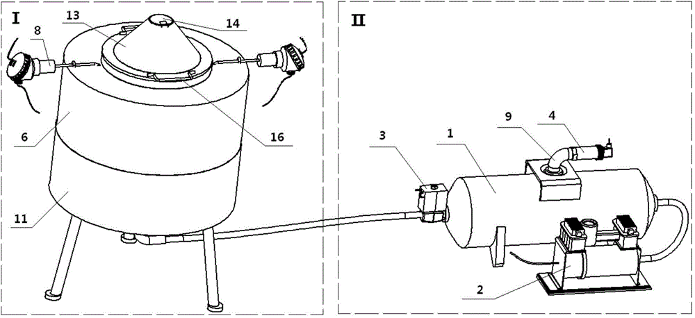
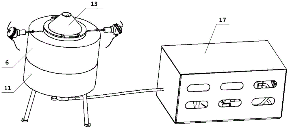
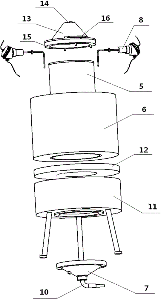
[0033] see figure 1 , the present invention structurally includes the blowback gas generation part I and the regeneration heating part II of the particle trap; The output end of the particle trap is connected to the regeneration heating part II of the particle trap through the solenoid valve 3; the regeneration heating part II of the particle trap includes a heater 6, and the heater 6 is installed on a base 11 with legs, and the bottom of the heater 6 passes through a disturbance The flow plate 7 is connected to the output end of the gas storage tank 1; the gas storage tank 1 is provided with a pressure transmitter 4 for collecting gas pressure in the tank, and a thermocouple 8 for detecting the heating temperature is installed inside the heater 6; The transmitter 4 and the thermocouple 8 are connected to an external controller, and the output signal of the ...


PUM


Abstract

A PM particle trap regeneration device comprises a backward-blow gas generation part and a particle trap regeneration heating part. The backward-blow gas generation part comprises a gas storage tank. The input end of the gas storage tank is connected with a gas pump, and the output end of the gas storage tank is connected with the particle trap regeneration heating part through an electromagnetic valve. The particle trap regeneration heating part comprises a heater capable of containing a particle trap inside. The bottom of the heater is connected with the output end of the gas storage tank through a spoiler. A pressure transmitter for collecting gas pressure in the tank is arranged on the gas storage tank. A thermal coupler for detecting the heating temperature is installed in the heater. The pressure transmitter and the thermal coupler are connected with an external controller. The controller outputs signals to control the electromagnetic valve to be opened and closed. The temperature is monitored in the whole process through the thermal coupler; when the combustion time is long enough and the gas pressure of the gas storage tank meets the requirements, the electromagnetic valve is automatically opened, the pressure gas is released for backward blowing, operation is easy and convenient, and the combustion of the particle trap is more accurately controlled.

Description

technical field [0001] The invention relates to an auxiliary equipment for purifying exhaust gas of a diesel engine, in particular to a regeneration equipment for a PM particulate trap. Background technique [0002] The PM particle filter has a high filtration efficiency for carbon, which can reach 60% to 90%. During the filtration, the particulate matter in the filter will cause the exhaust back pressure of the diesel engine to increase. At this time, the performance of the diesel engine begins to deteriorate, so the particles must be removed regularly to restore the trap to its original working state, that is, regeneration. Burner fuel injection heating regeneration and electric heating regeneration are relatively easy to realize on the electronic control system, but electric heating is more harmful to the battery, and it is not easy to realize on small and medium-sized vehicles, so the regeneration method of burner fuel injection heating is mainly studied. Currently, the...

Claims


Application Information

Patent Timeline
IPC IPC(8): F01N3/027
Inventor 张新荣王超孟繁星康广庆李壮
Owner CHANGAN UNIV
Why Eureka
Try Eureka